LDP135-151 Portrait Mode
From ViewSonic Documentation
Dual-Screen Splicing
The DirectView LED Display can be installed in either Landscape or Portrait orientation.
 |
| Landscape Installation |
 |
| Portrait Installation |
- NOTE: The System Control Boxes can be installed under the Cabinets (standard installation) for front access, or behind the Cabinets.
Wall Mounting
Installing the Wall Mount Brackets

- Ensure the wall area and size is an appropriate installation site.
- Using the first Wall Mount Bracket, install the top Wall Mount Bracket with the provided screws (M6x50mm Expansion for masonry; TA6x30mm for load bearing wood).
- Repeat Step 2, ensuring the second Wall Mount Bracket is level with the first Wall Mount Bracket. Keep a 47 ¹/₄" (1200 mm) space between the two brackets (as pictured above).
- Install the remaining two Wall Mount Brackets in the same manner as the other two Wall Mount Brackets. The distance between the Wall Mount Brackets is 47 ¹/₄" (1200 mm) and 19 ¹¹/₁₆" (500 mm) respectively.
Ensure the wall can safely support 297.62 lbs. (135 kg).
Ensure the deviation of the wall surface is < ¹³/₆₄" (< 5 mm).
Installing the Cabinets
- Ensure 10 Mounting Brackets are attached to the rear of the five (5) Middle Cabinets are positioned horizontally as shown below:
- Carefully lift each Cabinet up onto the Wall Mount Brackets, starting from the bottom.
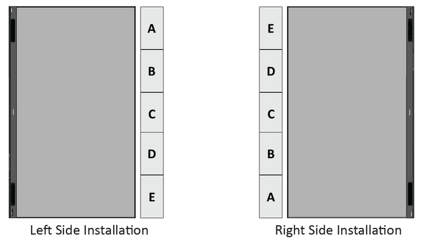
- NOTE: Cabinet letter installation will differ based on the preferred System Control Box installation (left or right side).
- Ensure the Mounting Brackets sit securely on the Wall Mount Brackets as shown below.
- Push each Locking Bolt and lock each Hook with the hex tool to securely connect each cabinet together. It may be necessary to align the hole with an Allen wrench in order to engage the Locking Bolt.
- NOTE: There are five (5) Locking Bolts and 10 Hooks between each cabinet.
- Further secure the Cabinets together with M6x16mm screws.
- Place the remaining Cabinets up onto the Wall Mount Brackets. Install from bottom to top, ensuring the Mounting Brackets sit securely on the Wall Mount Brackets.
- Repeat Step 4, securing the Cabinets together with each Locking Bolt and Hook.
- NOTE: There are five (5) Locking Bolts and 10 Hooks between each cabinet.
- Further secure the Cabinets together with M6x16mm screws.
- After installing all the Cabinets, the installation wall should look like:


