LDP135-151 Detachable System Control Box
From ViewSonic Documentation
Detachable System Control Box
The System Control Box can be installed under the Cabinets (standard installation) for front access, or behind the Cabinets.
 |
 |
| Standard Installation | Hidden System Control Box Installation |
- NOTE:
- Standard Installation video.
- Follow the below guide to install the display with the Hidden System Control Box layout.
Wall Mounting
Installing the Upper and Lower Wall Mount Brackets
Installing the Cabinets
Connecting the System Control Box (Hidden Installation)
- Carefully unfold the System Control Box panel. Ensure the main system control board is on the right.
- NOTE: Use caution as the System Control Box panel is separated into two pieces with wires attached.
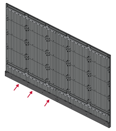
- Install the left part of System Control Box using the M6x16mm screws behind the Cabinet.
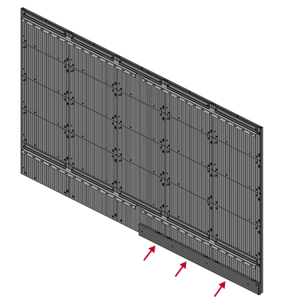
- Install the right part of the System Control Box using the M6x16mm screws behind the Cabinet.
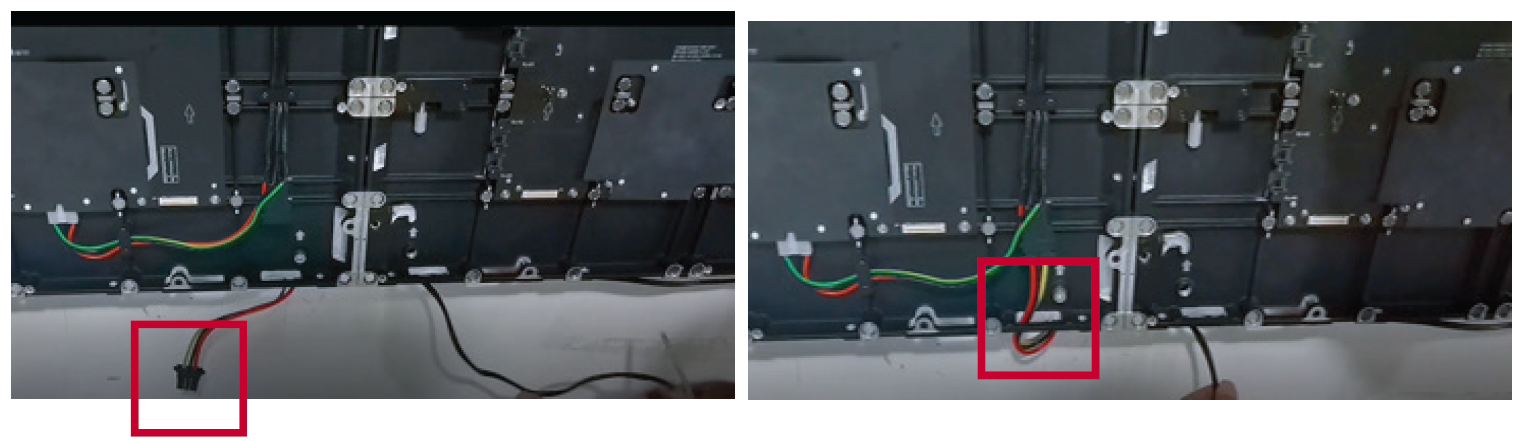
- Connect the Network and Power cables of the Cabinets to the System Control Box.
- NOTE: There are five (5) Network and five (5) Power cables to connect.
- Route the Power cable through the opening provided in the Cabinet and connect it to the power plug.
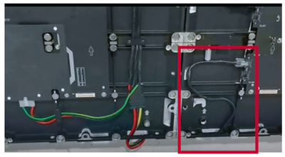
- Route the Network cable through the opening provided in the Cabinet into an “S-shape" and connect it to the network port.
- Install the bezels from the bottom of the screen and use the M6x10mm screws to secure it to the Cabinet.


Installing the LED Modules
Please wear Anti-Static Gloves before handling the LED modules.
- Install each LED Module onto the Cabinets, being sure to match the corresponding numbers on the Module to the Cabinet.
- Ensure each Module is flush and that there is little to no gap between each. It may be necessary to gently tap the module to make it flush.

