LDM231-251 Introduction: Difference between revisions
From ViewSonic Documentation
// via Wikitext Extension for VSCode |
No edit summary |
||
| (16 intermediate revisions by 2 users not shown) | |||
| Line 11: | Line 11: | ||
<div class="grid-item">[[LDM231-251_On-Screen_Display_Menu|On-Screen Display Menu]]</div> | <div class="grid-item">[[LDM231-251_On-Screen_Display_Menu|On-Screen Display Menu]]</div> | ||
<div class="grid-item">[[LDM231-251_Pre-installed_Applications|Pre-installed Applications]]</div> | <div class="grid-item">[[LDM231-251_Pre-installed_Applications|Pre-installed Applications]]</div> | ||
<div class="grid-item">[[LDM231-251_Specifications|Specifications]]</div> | <div class="grid-item">[[LDM231-251_Specifications|Specifications]]</div> | ||
<div class="grid-item">[[LDM231-251_Regulatory_and_Service_Information|Regulatory and Service Information]]</div> | <div class="grid-item">[[LDM231-251_Regulatory_and_Service_Information|Regulatory and Service Information]]</div> | ||
<div class="grid-item"><span class="newwin">[[LDM_RS-232_Protocol|'''RS-232 Protocol''']]</span></div> | |||
<div class="grid-item"><span class="newwin">[[Direct_View_LED_Display_Safety_Precautions|'''Safety Precautions''']]</span></div> | <div class="grid-item"><span class="newwin">[[Direct_View_LED_Display_Safety_Precautions|'''Safety Precautions''']]</span></div> | ||
<div class="grid-item"><span class="newwin">[[Direct_View_LED_Display_Troubleshooting|'''Troubleshooting''']]</span></div> | <div class="grid-item"><span class="newwin">[[Direct_View_LED_Display_Troubleshooting|'''Troubleshooting''']]</span></div> | ||
| Line 21: | Line 21: | ||
</div> | </div> | ||
</div> | </div> | ||
{{ | </noinclude> | ||
=Package Contents= | |||
{{Note| | |||
:*This product is packed in a wooden crate. | |||
:*Due to the size and weight, it is recommended that two or more people handle it. | |||
:*You can identify the contents inside the case by the product labels on it. | |||
}} | |||
<gallery caption="Standard Installation (the System Control Box installed Under the Cabinets)"> | <gallery caption="Standard Installation (the System Control Box installed Under the Cabinets)"> | ||
LDM231-251 IG.png |Installation Guide | LDM231-251 IG.png | <div style="font-style:normal; text-align:center;">Installation Guide</div> | ||
LDM231-251 Cabinets.svg | 8 x Cabinet Sections<br> | LDM231-251 Cabinets.svg | <div style="font-style:normal; text-align:center;"> 8 x Cabinet Sections<br></div> | ||
LDS135-151_LED_Module.svg |296 x LED Modules<ref>The quantity of spare LED modules varies by country.</ref> | LDS135-151_LED_Module.svg | <div style="font-style:normal; text-align:center;">296 x LED Modules<ref>The quantity of spare LED modules varies by country.</ref></div> | ||
LDM231-251 Screen Bezels Sides.svg |Screen Bezels<br>5 x Left & 5 x Right | LDM231-251 Screen Bezels Sides.svg | <div style="font-style:normal; text-align:center;">Screen Bezels,<br>5 x Left & 5 x Right<br> 2 x Bottom</div> | ||
LDM231-251 SCB.svg |System Control Box | LDM231-251 SCB.svg | <div style="font-style:normal; text-align:center;">System Control Box</div> | ||
LDM231-251 Connector Plate.svg |1 x System Control Box Connector Plate | LDM231-251 Connector Plate.svg | <div style="font-style:normal; text-align:center;">1 x System Control Box Connector Plate</div> | ||
LD-MK-004.svg |Maintenance Tool<br>P/N:LD-MK-004 | LD-MK-004.svg | <div style="font-style:normal; text-align:center;">Maintenance Tool<br>(P/N:LD-MK-004)</div> | ||
LDM231-251 Wall Mount Brackets STD.svg |Wall Mount Brackets<br> 8 x 1199 mm | LD-MK-006.svg| <div style="font-style:normal; text-align:center;">Suction Tool<br>(P/N: LD-MK-006)</div> | ||
LDM231-251 Wall Mount Connector Plate.svg |6 x Wall Mount Connector Plates | LDM231-251 Wall Mount Brackets STD.svg | <div style="font-style:normal; text-align:center;">Wall Mount Brackets,<br> 8 x 1199 mm</div> | ||
LDM231-251 Nuts and Bolts.svg |Nuts and Bolts | LDM231-251 Wall Mount Connector Plate.svg | <div style="font-style:normal; text-align:center;">6 x Wall Mount Connector Plates</div> | ||
LDM231-251 Hand Tools.svg |Hand Tools | LDM231-251 Nuts and Bolts.svg | <div style="font-style:normal; text-align:center;">Nuts and Bolts</div> | ||
LDS135-151_Gloves.svg|2 x Anti-Static Gloves | LDM231-251 Hand Tools.svg | <div style="font-style:normal; text-align:center;">Hand Tools</div> | ||
LDP216-251_Power_Cord.svg|2 x Power Cords<ref>Power consumption is large, so two power cords and two dedicated power outlets are required.</ref> | LDS135-151_Gloves.svg| <div style="font-style:normal; text-align:center;">2 x Anti-Static Gloves</div> | ||
LDM 231-251 Remote Control.svg |1 x Romote Control<br>With two AAA batteries | LDP216-251_Power_Cord.svg| <div style="font-style:normal; text-align:center;">2 x Power Cords<ref>Power consumption is large, so two power cords and two dedicated power outlets are required.</ref></div> | ||
LDP216-121_IR_Cable.svg|1 x IR Extension Cable | LDM 231-251 Remote Control.svg | <div style="font-style:normal; text-align:center;">1 x Romote Control<br>With two AAA batteries</div> | ||
M2_Dongle.png| 1 x USB Thumb Drive | LDP216-121_IR_Cable.svg| <div style="font-style:normal; text-align:center;">1 x IR Extension Cable</div> | ||
M2_Dongle.png| <div style="font-style:normal; text-align:center;"> 1 x USB Thumb Drive</div> | |||
</gallery> | </gallery> | ||
<gallery caption="Hidden Installation (the System Control Box installed Behind the Cabinets)"> | <gallery caption="Hidden Installation (the System Control Box installed Behind the Cabinets)"> | ||
LDM231-251 Screen Bezels Bottom.svg |Screen Bezels<br> 6 x Bottom | LDM231-251 Screen Bezels Bottom.svg | <div style="font-style:normal; text-align:center;">Screen Bezels,<br> 6 x Bottom</div> | ||
LDM231-251 Wall Mount Brackets Hidden.svg |Wall Mount Brackets<br>6 x 1335 mm | LDM231-251 Wall Mount Brackets Hidden.svg | <div style="font-style:normal; text-align:center;">Wall Mount Brackets,<br>6 x 1335 mm</div> | ||
LDM231-251 Upper SCB Mount Brackets.svg |2 x Upper System Control Box Mount Brackets | LDM231-251 Upper SCB Mount Brackets.svg | <div style="font-style:normal; text-align:center;">2 x Upper System Control Box Mount Brackets</div> | ||
LDM231-251 Lower SCB Mount Brackets.svg |2 x Lower System Control Box Mount Brackets | LDM231-251 Lower SCB Mount Brackets.svg | <div style="font-style:normal; text-align:center;">2 x Lower System Control Box Mount Brackets</div> | ||
LDM231-251 Cable Zip Ties.svg |24 x Cable Zip Ties | LDM231-251 Cable Zip Ties.svg | <div style="font-style:normal; text-align:center;">24 x Cable Zip Ties</div> | ||
LDM231-251 Power Cables Hidden.svg |Power Cables<br>2 x One-to-Three<br>1 x One-to-Two | LDM231-251 Power Cables Hidden.svg | <div style="font-style:normal; text-align:center;">Power Cables,<br>2 x One-to-Three &<br>1 x One-to-Two</div> | ||
LDP216-121_LAN_Cable.svg|4 x Network Cables (3.5 m) | LDP216-121_LAN_Cable.svg| <div style="font-style:normal; text-align:center;">4 x Network Cables (3.5 m)</div> | ||
</gallery> | </gallery> | ||
===Notes=== | |||
<references/> | <references/> | ||
=Product Overview= | =Product Overview= | ||
==Front Panel== | ==Front Panel== | ||
| Line 65: | Line 68: | ||
<div class="res-img">[[File:LDM231-251 Rear View.png |550px|alt=Rear Panel View]]</div> | <div class="res-img">[[File:LDM231-251 Rear View.png |550px|alt=Rear Panel View]]</div> | ||
=Control Panel and I/O= | =Control Panel and I/O= | ||
==Control Panel | ==Control Panel== | ||
<div class="res-img">[[File:LDM231-251 Control Panel and IO.png |550px|alt=LDM231-251's Control Panel and I/O]]</div> | <div class="res-img">[[File:LDM231-251 Control Panel and IO.png |550px|alt=LDM231-251's Control Panel and I/O]]</div> | ||
{| class="wikitable" style="text-align:center; background-color:#ffffff;" width="60%" | {| class="wikitable" style="text-align:center; background-color:#ffffff;" width="60%" | ||
|- | |- | ||
! style="font-weight:bold; background-color:#DB0025; color:#ffffff; width: | ! style="font-weight:bold; background-color:#DB0025; color:#ffffff; width:10%;"| Number | ||
! style="font-weight:bold; background-color:#DB0025; color:#ffffff; width:20%;"| Port | ! style="font-weight:bold; background-color:#DB0025; color:#ffffff; width:20%;"| Port | ||
! style="font-weight:bold; background-color:#DB0025; color:#ffffff;"| Description | ! style="font-weight:bold; background-color:#DB0025; color:#ffffff;"| Description | ||
| Line 91: | Line 94: | ||
|- | |- | ||
| style="font-weight:bold;" | 5 | | style="font-weight:bold;" | 5 | ||
| USB 2.0 | | '''USB 2.0''' | ||
| style="text-align:left;" | USB Reader (5V/0.5A). | | style="text-align:left;" | USB Reader (5V/0.5A). | ||
|- | |- | ||
| style="font-weight:bold;" | 6 | | style="font-weight:bold;" | 6 | ||
| Menu | | '''Menu''' | ||
| style="text-align:left;" | Open the display settings or On-Screen Display (OSD) Menu. | | style="text-align:left;" | Open the display settings or On-Screen Display (OSD) Menu. | ||
|- | |- | ||
| style="font-weight:bold;" | 7 | | style="font-weight:bold;" | 7 | ||
| Brightness/OK | | '''Brightness/OK''' | ||
| style="text-align:left;" | | | style="text-align:left;" | | ||
*Brightness adjustment button. | *Brightness adjustment button. | ||
| Line 105: | Line 108: | ||
|- | |- | ||
| style="font-weight:bold;" | 8 | | style="font-weight:bold;" | 8 | ||
| Brightness Decrease | | '''Brightness Decrease''' | ||
| style="text-align:left;" | Decrease the brightness level. | | style="text-align:left;" | Decrease the brightness level. | ||
|- | |- | ||
| style="font-weight:bold;" | 9 | | style="font-weight:bold;" | 9 | ||
| Brightness Increase | | '''Brightness Increase''' | ||
| style="text-align:left;" | Increase the brightness level. | | style="text-align:left;" | Increase the brightness level. | ||
|- | |- | ||
| style="font-weight:bold;" | 10 | | style="font-weight:bold;" | 10 | ||
| Power | | '''Power''' | ||
| style="text-align:left;" | Power on, standby and wake button. | | style="text-align:left;" | Power on, standby and wake button. | ||
|- | |- | ||
| style="font-weight:bold;" | 11 | | style="font-weight:bold;" | 11 | ||
| Indicator Light | | '''Indicator Light''' | ||
| style="text-align:left;" | Power status indicator light. | | style="text-align:left;" | Power status indicator light. | ||
|- | |- | ||
| style="font-weight:bold;" | 12 | | style="font-weight:bold;" | 12 | ||
| HDMI 4 | | '''HDMI 4''' | ||
| style="text-align:left;" | 4 High definition input: PIP/PBP, connect to PC with HDMI output, set-top box, or other video device. | | style="text-align:left;" | 4 High definition input: PIP/PBP, connect to PC with HDMI output, set-top box, or other video device. | ||
|- | |- | ||
| style="font-weight:bold;" | 13 | | style="font-weight:bold;" | 13 | ||
| Audio Out | | '''Audio Out''' | ||
| style="text-align:left;" | Audio output to an external audio device. | | style="text-align:left;" | Audio output to an external audio device. | ||
|} | |} | ||
| Line 132: | Line 135: | ||
<div class="res-img">[[File:LDM231-251 IO Ports.png |550px|alt=LDM231-251's I/O ports]]</div> | <div class="res-img">[[File:LDM231-251 IO Ports.png |550px|alt=LDM231-251's I/O ports]]</div> | ||
{| class="wikitable" style="text-align:center; background-color:#ffffff;" width="60%" | |||
|- | |||
! colspan="2" style="font-weight:bold; background-color:#DB0025; color:#ffffff;" | Item | |||
! style="font-weight:bold; background-color:#DB0025; color:#ffffff;"| Description | |||
|- | |||
| style="font-weight:bold;" | 1 | |||
| '''S/PDIF Out''' | |||
| style="text-align:left;" | Multi-channel optical audio signal. | |||
|- | |||
| style="font-weight:bold;" | 2 | |||
| '''Audio OUT''' | |||
| style="text-align:left;" | Audio output to an external speaker. | |||
|- | |||
| style="font-weight:bold;" | 3 | |||
| '''LAN''' | |||
| style="text-align:left;" | Standard RJ45 (10M/100M/1000M) Internet connection interface. | |||
|- | |||
| style="font-weight:bold;" | 4 | |||
| '''RJ45''' | |||
| style="text-align:left;" | Standard RJ45 control connection interface. | |||
|- | |||
| style="font-weight:bold;" | 5 | |||
| '''HDMI 1/2/3''' | |||
| style="text-align:left;" | High definition input: PIP/PBP ,connect to PC with HDMI output, set-top box, or other video device. | |||
|- | |||
| style="font-weight:bold;" | 6 | |||
| '''HDMI Out''' | |||
| style="text-align:left;" | Extend the display's content out to another display device. | |||
|- | |||
| style="font-weight:bold;" | 7 | |||
| '''USB 2.0''' | |||
| style="text-align:left;" | USB Type A port for power (5V/2A). | |||
|- | |||
| style="font-weight:bold;" | 8 | |||
| '''HDMI IN 1.4''' | |||
| style="text-align:left;" | <p>High definition input: PIP/PBP ,connect to PC with HDMI output, set-top box, or other video device.</p> | |||
:'''NOTE:''' This port can also be accessed without removing the System Control Box Cover. | |||
|- | |||
| style="font-weight:bold;" | 9 | |||
| '''Audio Out''' | |||
| style="text-align:left;" | <p>Audio output to an external audio device.</p> | |||
:'''NOTE:''' This port can also be accessed without removing the System Control Box Cover. | |||
|- | |||
| style="font-weight:bold;" | 10 | |||
| '''IR Extension''' | |||
| style="text-align:left;" | Connection point for an extended IR receiver. | |||
|- | |||
| style="font-weight:bold;" | 11 | |||
| '''RS-232''' | |||
| style="text-align:left;" | Serial control port. | |||
|- | |||
| style="font-weight:bold;" | 12 | |||
| '''Control Board Switch''' | |||
| style="text-align:left;" | <p>Control switch for the control board.</p> | |||
:'''NOTE:''' Make sure to switch to the left for RS-232 control. | |||
|- | |||
|} | |||
Latest revision as of 06:48, 23 January 2026
Package Contents
Note:
- This product is packed in a wooden crate.
- Due to the size and weight, it is recommended that two or more people handle it.
- You can identify the contents inside the case by the product labels on it.
- Standard Installation (the System Control Box installed Under the Cabinets)
-
 Installation Guide
 -
 8 x Cabinet Sections
 -
![296 x LED Modules[1]](/images/9/9d/LDS135-151_LED_Module.svg) 296 x LED Modules[1]
296 x LED Modules[1] -
 Screen Bezels,
5 x Left & 5 x Right
2 x Bottom -
 System Control Box
 -
 1 x System Control Box Connector Plate
 -
 Maintenance Tool
(P/N:LD-MK-004) -
 Suction Tool
(P/N: LD-MK-006) -
 Wall Mount Brackets,
8 x 1199 mm -
 6 x Wall Mount Connector Plates
 -
 Nuts and Bolts
 -
 Hand Tools
 -
 2 x Anti-Static Gloves
 -
![2 x Power Cords[2]](/images/6/62/LDP216-251_Power_Cord.svg) 2 x Power Cords[2]
2 x Power Cords[2] -
 1 x Romote Control
With two AAA batteries -
 1 x IR Extension Cable
 -
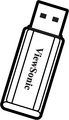 1 x USB Thumb Drive

![296 x LED Modules[1]](/File:LDS135-151_LED_Module.svg)


- Hidden Installation (the System Control Box installed Behind the Cabinets)
-
 Screen Bezels,
6 x Bottom -
 Wall Mount Brackets,
6 x 1335 mm -
 2 x Upper System Control Box Mount Brackets
 -
 2 x Lower System Control Box Mount Brackets
 -
 24 x Cable Zip Ties
 -
 Power Cables,
2 x One-to-Three &
1 x One-to-Two -
 4 x Network Cables (3.5 m)


Notes
Product Overview
Front Panel

Rear Panel

Control Panel and I/O
Control Panel

| Number | Port | Description |
|---|---|---|
| 1 | Light Sensor | Ambient light sensor. |
| 2 | IR Receiver | Receiver for remote control signal. |
| 3 | USB Type C | USB 2.0 support (5V/1.0A). |
| 4 | USB 3.0 | USB Reader (5V/0.9A). |
| 5 | USB 2.0 | USB Reader (5V/0.5A). |
| 6 | Menu | Open the display settings or On-Screen Display (OSD) Menu. |
| 7 | Brightness/OK |
|
| 8 | Brightness Decrease | Decrease the brightness level. |
| 9 | Brightness Increase | Increase the brightness level. |
| 10 | Power | Power on, standby and wake button. |
| 11 | Indicator Light | Power status indicator light. |
| 12 | HDMI 4 | 4 High definition input: PIP/PBP, connect to PC with HDMI output, set-top box, or other video device. |
| 13 | Audio Out | Audio output to an external audio device. |
I/O Ports

| Item | Description | |
|---|---|---|
| 1 | S/PDIF Out | Multi-channel optical audio signal. |
| 2 | Audio OUT | Audio output to an external speaker. |
| 3 | LAN | Standard RJ45 (10M/100M/1000M) Internet connection interface. |
| 4 | RJ45 | Standard RJ45 control connection interface. |
| 5 | HDMI 1/2/3 | High definition input: PIP/PBP ,connect to PC with HDMI output, set-top box, or other video device. |
| 6 | HDMI Out | Extend the display's content out to another display device. |
| 7 | USB 2.0 | USB Type A port for power (5V/2A). |
| 8 | HDMI IN 1.4 | High definition input: PIP/PBP ,connect to PC with HDMI output, set-top box, or other video device.
|
| 9 | Audio Out | Audio output to an external audio device.
|
| 10 | IR Extension | Connection point for an extended IR receiver. |
| 11 | RS-232 | Serial control port. |
| 12 | Control Board Switch | Control switch for the control board.
|