LDM231-251 Wall Installation
Wall Installation
Introduction
The step-by-step instructions in this guide are a general reference for installing the LED Display. If any details in this document are unclear, please contact your reseller for more information.
About the LED Display
ViewSonic Direct View LDM231-251 is designed to be installed on the wall only. However, the System Control Box can be mounted in three different ways.
-
 Under the Cabinets
(Standard Installation) -
 Behind the Cabinets
(Hidden Installation) -
 Away from the Cabinets
(Separate Installation)


Before Installing
Ensure there is no direct airflow from air conditioning or heating vents blowing on the display.
Avoid installing the LED Display in places with high humidity.
Due to high power usage, always use power cords specifically designed for this product.
Wood may split if holes are not pre-drilled before installing the Wall Mount Brackets.
Ensure that the wall can safely support 378 kg and the power outlet supplies enough voltage (max: 4124W; normal: 1443W).
Ensure the deviation of the wall surface is < 5 mm.
Wear protective gear, such as gloves and protective shoes, when handling the LED Display.
Standard Installation
Wall Mounting
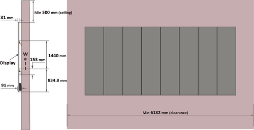
Eight Wall Mount Brackets are used for mounting the screen to the wall.
-
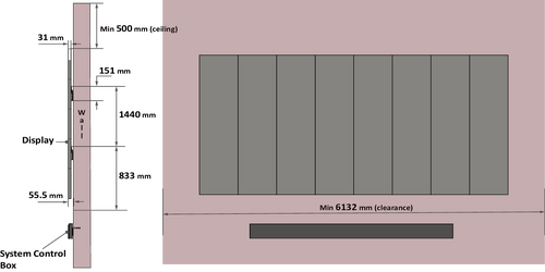
Ensure the wall area is an appropriate installation site.
 Note:
Note:- You can also install the Upper Wall Mount Brackets, hang the screen, and then install the Lower Wall Mount Brackets for a more precise fit.
- Adjustment in floor clearance and ceiling height should be made according to the actual installation site.
-
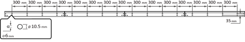
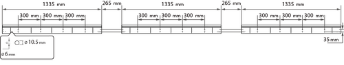
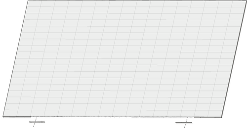
Using the illustration as shown below as a guide, mark at least eight mounting holes and pre-drill them.
- Install the first Upper Wall Mount Bracket with the provided screws (M8 x 80 mm Expansion for masonry; wood screws for load bearing wood).
- Repeat Step 2~3, ensuring the second Upper Wall Mount Bracket is level with the first Upper Bracket.
Note: It is recommended to use a laser or torpedo level.
-
After mounting the first and second Upper Wall Mount Brackets to the wall, secure them with the Wall Mount Connector Plate using the six provided screws (PM6 x 10 mm).

-
Repeat Step 2~5 for the remaining two Upper Wall Mount Brackets.

- Install the Lower Wall Mount Brackets in the same manner as the Upper Wall Mount Brackets. The distance between the Upper and Lower Wall Mount Brackets is 1440 mm.
-
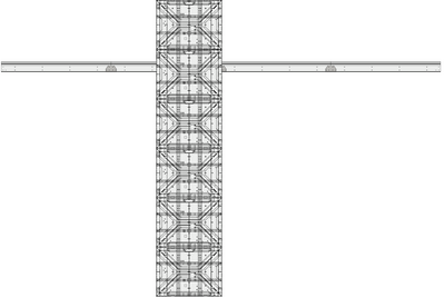
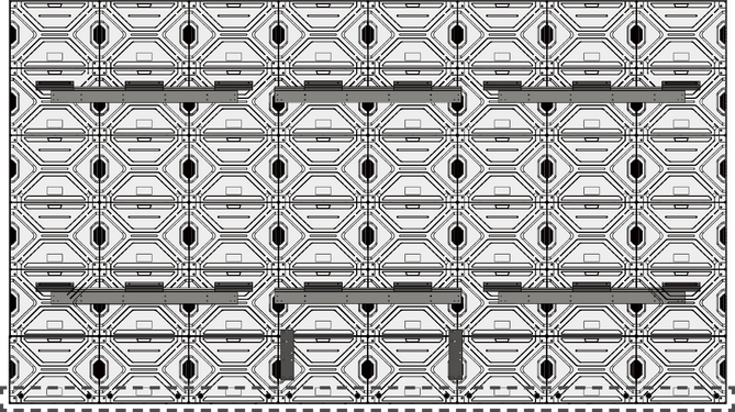
After installing both Upper and Lower Wall Mount Brackets, the installation wall should look like:


Installing the Cabinets
-
Place the Upper Cabinet section "D-1" and Lower Cabinet section "D-2" on stable furniture that can safely support the two Cabinet sections.
Note:- One Cabinet is separated into two sections. Each section weighs around 18.6 kg (41 lb).
- You can identify Cabinet sections by the labels on the package.
- The arrow marks on each Cabinet section should be pointing up.
-
Attach the Upper and Lower Cabinet sections with the two provided screws (M8 x 20 mm).

-
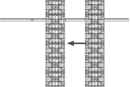
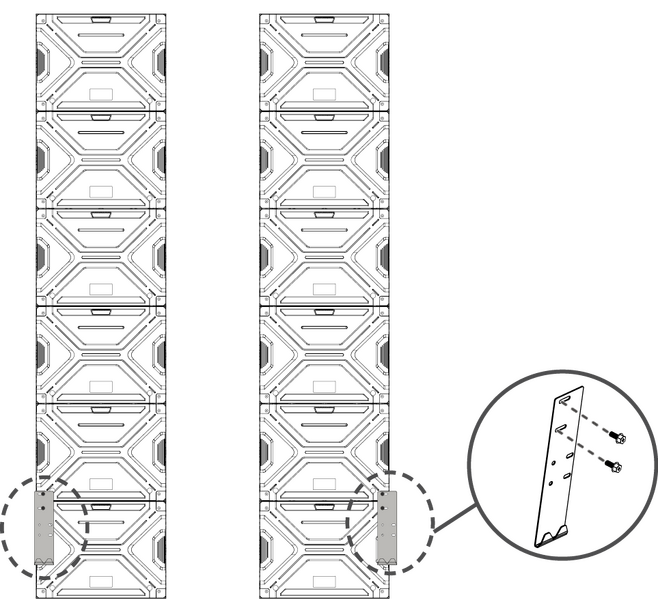
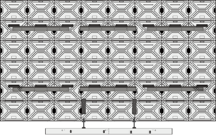
Carefully lift the assembled Cabinet "D" onto the center of the Upper Wall Mount Brackets.
-
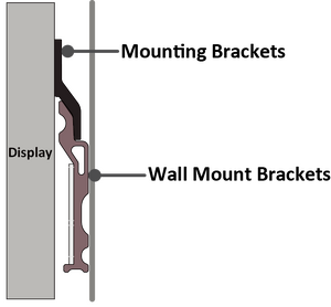
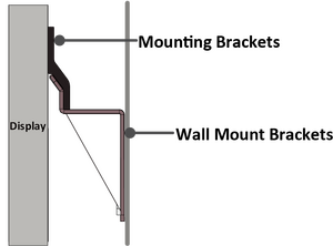
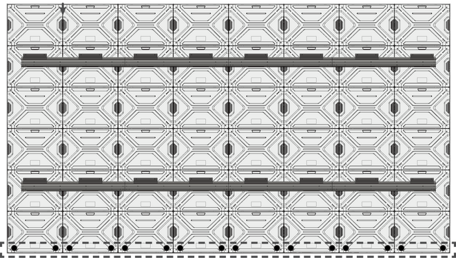
Ensure the Mounting Brackets sit securely on the Wall Mount Brackets as shown below.
-
Repeat Step 1~2 for Cabinet "E".
-
Install the assembled Cabinet "E" on the right side of Cabinet "D" with the provided screws (M8 x 20 mm).
 Note: There are 12 screws between each Cabinet.
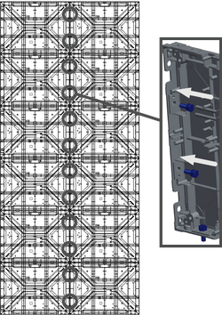
-
Check for unevenness of the Cabinets by rubbing the cross section between each Cabinet. If the cross section is not aligned, loosen the M8 screws slightly and tap the Cabinets until the cross section is flat.
-
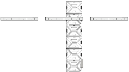
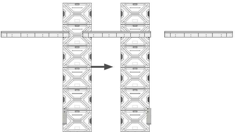
Repeat Step 1~2 for the remaining Cabinets and install them onto the Wall Mount Brackets. Start from the center to the right and left sides of the Wall Mount Brackets.
Note: The installation sequence by Cabinet: D ➜ E ➜ C ➜ F ➜ B ➜ G ➜ A ➜ H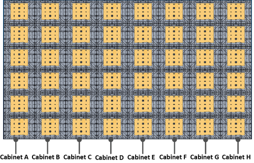


Connecting the System Control Box
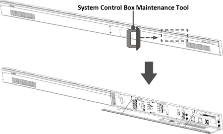
The left and right sides of the System Control Box are pre-installed with its Covers in the factory. The main system control board is on the right.
The safety wires are used to prevent the Right Cover from falling when accessing the System Control Box. Please ensure that the safety wires are never removed.
Use caution as the System Control Box panel is separated into two pieces with wires attached.

-
Carefully place the System Control Box on stable furniture that can safely support the System Control Box.
-
To open the Right Cover, slowly bring the supplied System Control Box Maintenance Tool near the surface of the Right Cover where the steel plate is located. Then, the Right Cover should detach from the System Control Box magnetically.
DO NOT try to remove or disconnect the safety wires. Please ensure that the safety wires are never removed.
-
Remove the Left Cover by gripping the top edge of the Cover and pulling it toward you. The Left Cover should simply lift away.

-
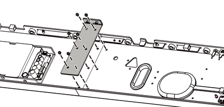
Secure the System Control Box panel with the Connector Plate using the provided screws (M3 x 6 mm).
-
Further secure the Connector Plate with the two provided screws (M3 x 5 mm).
-
Align the holes of the Cabinets with the System Control Box to attach.
-
Carefully route the Network and Power Cables through the holes in each Cabinet.
-
Install the System Control Box to the bottom of the Cabinets with the provided screws (M8 x 20 mm).
Note: There are seven threaded holes between the Cabinets and the System Control Box.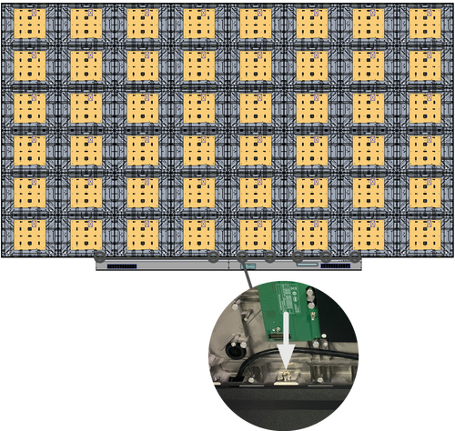
-
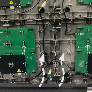
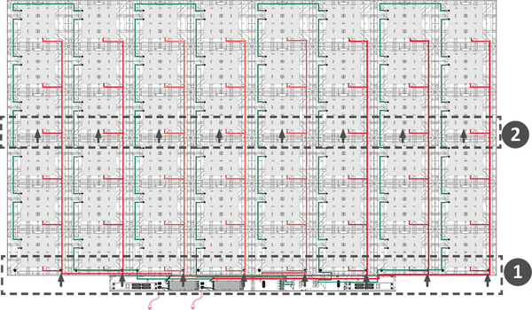
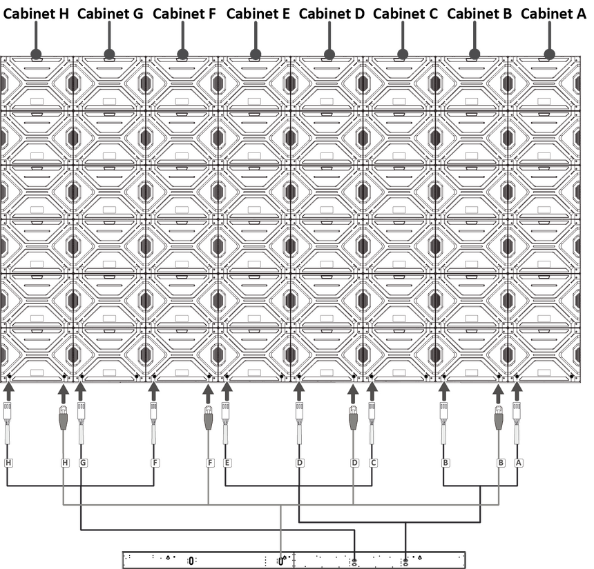
Connect the Network Cables (Green) of the Cabinets. Start from the bottom and move to the top.
- Connect the four Network Cables from the System Control Box to Cabinet "B", "D", "F", and "H".
Note: Ensure to match the corresponding letters on the Network Cables to the Cabinets (B to B, D to D, F to F, and H to H).
- Connect the Network Cables of the eight Lower Cabinet sections to their Upper Cabinet sections.
- At the top row, connect the Network Cable of the first Cabinet to the next Cabinet.
Note: There are four Network Cables to connect.

- Connect the four Network Cables from the System Control Box to Cabinet "B", "D", "F", and "H".
-
Connect the Power Cables (Red/Orange) of the Cabinets. Start from the bottom and move to the top.
- Connect the Power Cables from the System Control Box to the eight Cabinets.
Note: Ensure to match the corresponding letters on the Cables to the Cabinets (A to A, B to B, C to C, D to D, and so on).
- Connect the Power Cables of the eight Lower Cabinet sections to their Upper Cabinet sections.
Note: There are eight Power Cables to connect.
- Connect the Power Cables from the System Control Box to the eight Cabinets.
-
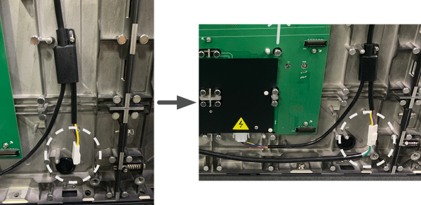
Connect the two AC units of the System Control Box to the main system control board.
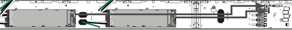
-
Connect the LED Display's left speaker to the Audio Out port.
 Note: Ensure that the right speaker is properly connected to the other Audio Out port.
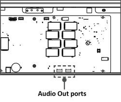
-
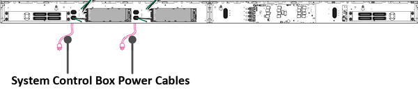
Ensure the two AC units of the System Control Box is properly connected.
DO NOT connect the System Control Box Power Cables at this time.
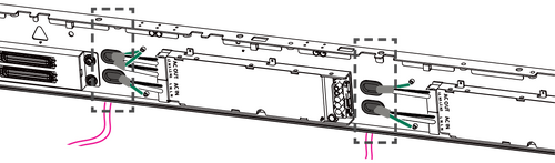
- The neutral wires (usually white/blue) are connected to the "N1", "N2", and "N" terminals.
- The hot wires (usually black/brown) are connected to the "L1", "L2", and "L" terminals.
- The input and output terminals are properly grounded (3 x AC OUT and 2 x AC IN, usually in green).
The meaning of wiring color may vary by country.

-
After connecting all Cables and wires, hold the top edge of the Right Cover toward the System Control Box to replace it. Once the Right Cover is replaced, it will be held in place magnetically.
Note: Ensure the Power Button cable is connected before securing the Right Cover.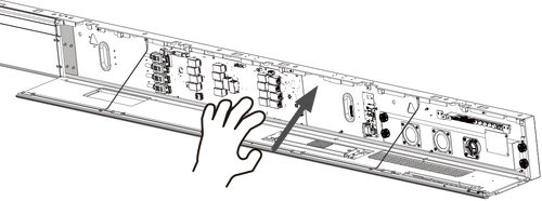
-
Replace the Left Cover by aligning it properly with the System Control Box; then the Left Cover should attach magnetically.


Installing the LED Modules
Please wear Anti-Static Gloves before handling the LED Modules.
To avoid direct contact with the LED Modules, please remove watches, rings, bracelets, or other metal objects.
Use caution when installing the LED Modules.
-
Starting from the LED Module labeled "1" in the top left corner, align each LED Module with the Cabinet, then carefully press the Module into place.
Note: The arrow marks on the back of the LED Modules should be pointing up.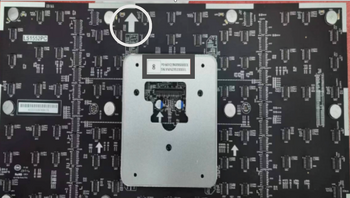
-
Attach the remaining LED Modules onto the Cabinets. Install from top left and move to bottom right, ensuring to match the corresponding numbers on the Module to the Cabinet.
 Note: Before installing the LED Module, ensure that each Module is flush and that there is little to no gap between each. It may be necessary to gently tap the module to make it flush.


Installing the Screen Bezels
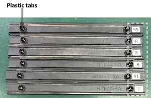
The Screen Bezels' plastic tabs are pre-installed onto the Bezels. Ensure all plastic tabs are properly mounted before installing the Screen Bezels onto the screen.
The label indicates the top of each Screen Bezel. To ensure the Bezels are installed in the correct position, please use the labels on the inside of the Bezels as a guide.

-
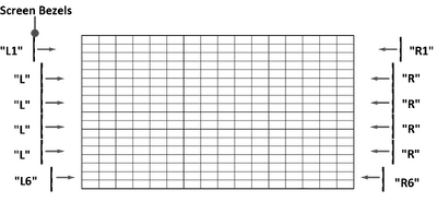
Place the Screen Bezel to the correct side of the screen to attach. Start from the left and move to the right.
Note:- Ensure the label side of the Screen Bezel is facing the screen.
- Before installing the Screen Bezels, check the label of each Bezel as the label helps you know which side ("L" = left side & "R" = right side) to attach.
- The illustration below shows the location where each Screen Bezel should be installed.
-
Align the plastic tabs of the Screen Bezel with the holes provided in the screen.

-
Press down on the Screen Bezel until you hear it click into place.
-
Place the remaining Screen Bezels onto the left and right sides of the screen.
Note: There are six Screen Bezels on either left or right side of the screen to install.


Turning On the LED Display
-
Make sure the System Control Box Power Cables are connected and plugged into power outlets.
 Note: When the System Control Box Power Cables are connected to power outlets, the Power Indicator Light will be a steady red. This means the LED Display is in standby mode. Please refer to the User Guide for more details.
 -
Your LED Display is now ready to power on.

Hidden Installation
When the System Control Box is installed behind the Cabinets, this installation type requires a different set of Wall Mount Brackets. You also need the System Control Box Mount Brackets to attach the System Control Box to the rear of the Cabinets.
Wall Mounting
Six Wall Mount Brackets are used for mounting the screen to the wall.
-
Ensure the wall area is an appropriate installation site.
 Note:
Note:- You can also install the Upper Wall Mount Brackets, hang the screen, and then install the Lower Wall Mount Brackets for a more precise fit.
- Adjustment in floor clearance and ceiling height should be made according to the actual installation site.
-
Using the illustration as shown above as a guide, mark at least eight mounting holes and pre-drill them.
-
Install the first Upper Wall Mount Bracket with the provided screws (M8 x 80 mm Expansion for masonry; wood screws for load bearing wood).
-
Repeat Step 2~3, ensuring the second Upper Wall Mount Bracket is level with the first Upper Bracket.
Note: It is suggested to use a laser or torpedo level. -
Install the third Upper Wall Mount Bracket in the same manner as the other two Upper Wall Mount Brackets.
-
Repeat Step 2~5 for the Lower Wall Mount Brackets. The distance between the Upper and Lower Wall Mount Brackets is 1440 mm.
-
After installing both Upper and Lower Wall Mount Brackets, the installation wall should look like:


Installing the Cabinets
Before installing the System Control Box behind the Cabinets, the Upper System Control Box Mount Bracket must be mounted to the Cabinets first.
-
Place the Upper Cabinet section "D-1" and Lower Cabinet section "D-2" on stable furniture that can safely support the two Cabinet sections.
Note:- One Cabinet is separated into two sections. Each section weighs around 18.6 kg.
- You can identify Cabinet sections by the labels on the package.
- The arrow marks on each Cabinet section should be pointing up.
-
Attach the Upper and Lower Cabinet sections with the two provided screws (M8 x 20 mm).
-
Repeat Step 1~2 for Cabinet "E".
-
Install the Upper System Control Box Mount Bracket to the side of the two assembled Cabinets "D" and "E" as shown below using the provided screws (M8 x 20 mm).
-
 Rear View of Cabinet "E" (left) and Cabinet "D" (right)
-
-
Carefully lift the assembled Cabinet "D" onto the center of the Upper Wall Mount Brackets.
-
Ensure the Mounting Brackets sit securely on the Wall Mount Brackets as shown below.
-
Install the assembled Cabinet "E" on the right side of the Cabinet "D" with the provided screws (M8 x 20 mm).
-
 Rear View of Cabinet "E" (left) and Cabinet "D" (right)
Note: There are 12 screws between each Cabinet. -
-
Check for unevenness of the Cabinets by rubbing the cross section between each Cabinet. If the cross section is not aligned, loosen the M8 screws slightly and tap the Cabinets until the cross section is flat.
-
Repeat Step 1~2 for the remaining Cabinets and install them onto the Wall Mount Brackets. Start from the center to the right and left sides of the Wall Mount Brackets.
Note: The installation sequence by Cabinet: D ➜ E ➜ C ➜ F ➜ B ➜ G ➜ A ➜ H


Connecting the System Control Box
The left and right sides of the System Control Box are pre-installed with its Covers in the factory. The main system control board is on the right.
The safety wires are used to prevent the Right Cover from falling when accessing the System Control Box. Please ensure that the safety wires are never removed.
Use caution as the System Control Box panel is separated into two pieces with wires attached.
Before installing the System Control Box, the Power and Network Cables of the Cabinets pre-installed in the System Control Box must be replaced with the longer ones first.
-
Carefully place the System Control Box on stable furniture that can safely support the System Control Box.
-
To open the Right Cover, slowly bring the supplied System Control Box Maintenance Tool near the surface of the Right Cover where the steel plate is located. Then, the Right Cover should detach from the System Control Box magnetically.
DO NOT try to remove or disconnect the safety wires. Please ensure that the safety wires are never removed.
-
Remove the Left Cover by gripping the top edge of the Cover and pulling it toward you. The Left Cover should simply lift away.
-
Secure the System Control Box panel with the Connector Plate using the provided screws (M3 x 6 mm).
-
Further secure the Connector Plate with the two provided screws (M3 x 5 mm).
-
Install the short side of the Lower System Control Box Mount Bracket onto the top of the System Control Box with the provided screws (M3 x 6 mm).
-
 Installing the Lower System Control Box Mount Brackets onto the System Control Box (Front and Top Views)
-
-
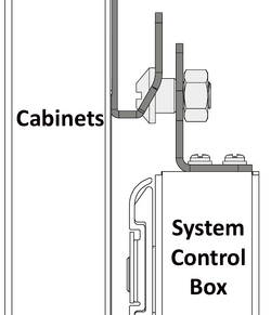
Install the provided screw (M8 x 16 mm) on the Lower System Control Box Mount Bracket. Thread the provided M8 nut onto the screw and fully tighten the nut.
-
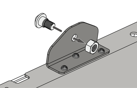 Installing the provided screw and nut to the Brackets (Rear View)
-
-
Repeat Step 7 for the other Lower System Control Box Mount Bracket.
-
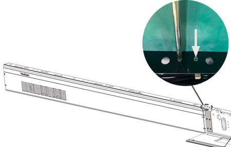
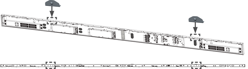
The rubber hole plugs installed on both the System Control Box and Cabinets are used to protect the Cables from rubbing against any pointed edges. Use a knife to cut the hole to size along the cross.
-
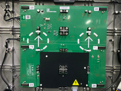
 System Control Box (Front View)
-
 Cabinets (Rear View)
-
-
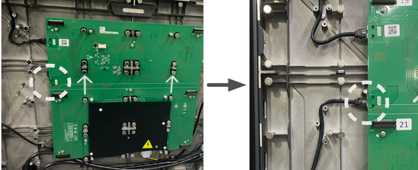
Remove the pre-installed Power and Network Cables of the Cabinets from the System Control Box.
Note:- There are eight Power and four Network Cables to remove.
- It is recommended to take photos of the completed wiring in the left and main system control boards before removing the Cables.
-
After removing the pre-installed Power and Network Cables of the Cabinets, connect one end of the longer Network Cable to the network port that was disconnected from the System Control Box in Step 10.
Note:- There are four Network Cables to connect.
- Ensure to match the corresponding letters on the Cables to the network ports of the System Control Box (B to B, D to D, F to F, and H to H).
-
Carefully thread the four Network Cables through the hole provided in the System Control Box to the rear. Avoid sharp bends in the Cables.
Note: The rubber hole plugs must always be placed in the holes.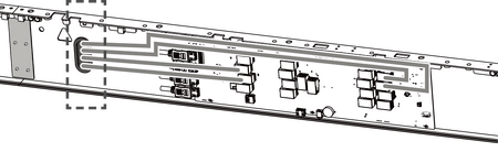
-
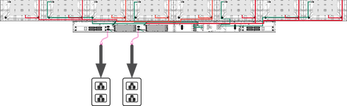
After threading the Network Cables, please follow the diagram below to connect the longer Power Cables to the two AC units of the System Control Box.
DO NOT connect the System Control Box Power Cables at this time.
- Connect the neutral wires (usually white/blue) to the "N1", "N2", and "N" terminals.
- Connect the hot wires (usually black/brown) to the "L1", "L2", and "L" terminals.
- Connect the ground wires (usually in green) to the ground terminals.
The meaning of wiring color may vary by country.
Use the provided wrench to tighten the neutral, hot, and ground conductors in the terminals properly.
-
Thread the Power Cables of the Cabinets through the hole provided in the System Control Box to the rear. Avoid sharp bends in the Cables.
Note:- There are three Power Cables to thread.
- The rubber hole plugs must always be placed in the holes.
- Before threading the Cables through, ensure that the output and input terminals (3 x AC OUT and 2 x AC IN) are properly grounded, and that the wire colors/labels are matched with the marked terminals and each wire is screwed firmly to its corresponding terminal.
-
Connect the two AC units of the System Control Box to the main system control board.
-
Connect the LED Display's left speaker to the Audio Out port.
Note: Ensure that the right speaker is properly connected to the other Audio Out port. -
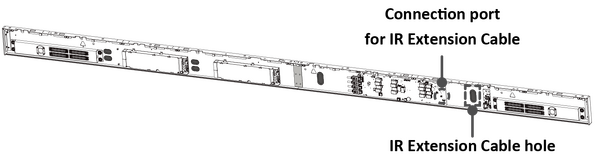
After the IR Extension Cable is connected, route it through the hole of the System Control Box to the rear.
-
After connecting all Cables and wires, hold the top edge of the Right Cover toward the System Control Box to replace it. Once the Right Cover is replaced, it will be held in place magnetically.
Note: Ensure the Power Button cable is connected before securing the Right Cover. -
Replace the Left Cover by aligning it properly with the System Control Box; then the Left Cover should attach magnetically.
-
Align the Lower System Control Box Mount Brackets with the Upper Mount Brackets to attach.
-
Thread the Power and Network Cables through the holes at the lowest row of the Cabinets to the front.
Note:- There are eight Power and four Network Cables to thread.
- Ensure the corresponding letters on both Cables are matched to the Cabinets (A to A, B to B, C to C, and so on).
-
 Threading the Power and Network Cables from behind (Rear View)
-
Carefully place the Lower System Control Box Mount Brackets onto the Upper System Control Box Mount Brackets.
Note: To avoid sharp bends in the Cables, please pull them into the Cabinets and manage the Cables there.-
 Placing the Lower System Control Box Mount Brackets to the Upper (Rear View)
-
-
Ensure the Lower System Control Box Mount Brackets sit securely on the Upper.
-
Connect the Network Cables (Green) of the Cabinets. Start from the bottom and move to the top.
- Connect the four Network Cables from the System Control Box to Cabinet "B", "D", "F", and "H".
Note: Ensure to match the corresponding letters on the Network Cables to the Cabinets (B to B, D to D, F to F, and H to H).
- Connect the Network Cables of the eight Lower Cabinet sections to their Upper Cabinet sections.
- At the top row, connect the Network Cable of the first Cabinet to the next Cabinet.
Note: There are four Network Cables to connect.
- Connect the four Network Cables from the System Control Box to Cabinet "B", "D", "F", and "H".
-
Connect the Power Cables (Red/Orange) of the Cabinets. Start from the bottom and move to the top.
- Connect the Power Cables from the System Control Box to the eight Cabinets.
Note: Ensure to match the corresponding letters on the Cables to the Cabinets (A to A, B to B, C to C, D to D, and so on).
- Connect the Power Cables of the eight Lower Cabinet sections to their Upper Cabinet sections.
Note: There are eight Power Cables to connect.
- Connect the Power Cables from the System Control Box to the eight Cabinets.
-
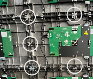
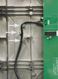
Route the Power and Network Cables around the rods provided in the Cabinets and secure the Cables to the rods with the Cable Zip Tie and screw (PM3 x 10 mm). Leave a little slack for later adjustments if needed.


Installing the LED Modules
Please wear Anti-Static Gloves before handling the LED Modules.
To avoid direct contact with the LED Modules, please remove watches, rings, bracelets, or other metal objects.
Use caution when installing the LED Modules.
-
Starting from the LED Module labeled "1" in the top left corner, align each LED Module with the Cabinet, then carefully press the Module into place.
Note: The arrow marks on the back of the LED Modules should be pointing up. -
Attach the remaining LED Modules onto the Cabinets. Install from top left and move to bottom right, ensuring to match the corresponding numbers on the Module to the Cabinet.
Note: Before installing the LED Module, ensure that each Module is flush and that there is little to no gap between each. It may be necessary to gently tap the module to make it flush.
Installing the Screen Bezels
The Screen Bezels' plastic tabs are pre-installed onto the Bezels. Ensure all plastic tabs are properly mounted before installing the Screen Bezels onto the screen.
The label indicates the top of each Screen Bezel. To ensure the Bezels are installed in the correct position, please use the labels on the inside of the Bezels as a guide.
-
Place the Screen Bezel to the correct side of the screen to attach. Start from the left and move to the right.
Note:- Ensure the label side of the Screen Bezel is facing the screen.
- Before installing the Screen Bezels, check the label of each Bezel as the label helps you know which side ("L" = left side & "R" = right side) to attach.
- The illustration below shows the location where each Screen Bezel should be installed.

-
Align the plastic tabs of the Screen Bezel with the holes provided in the screen.
-
Press down on the Screen Bezel until you hear it click into place.
-
Place the remaining Screen Bezel onto the left and right sides of the screen.
-
At the bottom of the screen, loosen the screws securing the pre-installed Screen Bezel and remove it. This provides enough room to the bottom Screen Bezels.
Note:- There are two pre-installed Screen Bezels to remove.
- The pre-installed Screen Bezels come in with two different lengths. Remove the shorter ones.
-
Install the bottom Screen Bezel to the screen with the four provided screws (M3 x10 mm).
Note: There are six bottom Screen Bezels to install.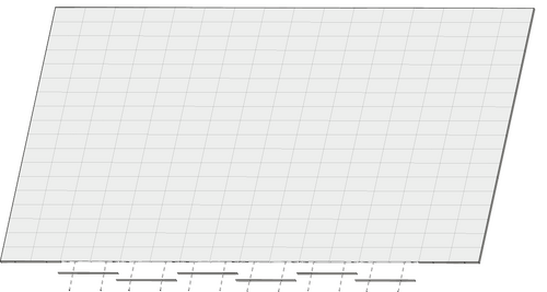


Turning On the LED Display
-
Make sure the System Control Box Power Cables are connected and plugged into power outlets.
Note: When the System Control Box Power Cables are connected to power outlets, the Power Indicator Light will be a steady red. This means the LED Display is in standby mode. Please refer to the User Guide for more details. -
Your LED Display is now ready to power on.
Separate Installation
When the System Control Box is installed apart from the Cabinets, this installation type shares the same Wall Mount Brackets as the Standard Installation. However, you will need to pre-drill additional holes for the System Control Box.
Wall Mounting
Eight Wall Mount Brackets are used for mounting the screen to the wall.
-
Ensure the wall area is an appropriate installation site.
 Note:
Note:- You can also install the Upper Wall Mount Brackets, hang the screen, and then install the Lower Wall Mount Brackets for a more precise fit.
- Adjustment in floor clearance and ceiling height should be made according to the actual installation site.
-
Using the illustration as shown below as a guide, mark at least eight mounting holes and pre-drill them.
- Install the first Upper Wall Mount Bracket with the provided screws (M8 x 80 mm Expansion for masonry; wood screws for load bearing wood).
- Repeat Step 2, ensuring the second Upper Wall Mount Bracket is level with the first Upper Bracket.
Note: It is recommended to use a laser or torpedo level.
-
After mounting the first and second Upper Wall Mount Brackets to the wall, secure them with the Wall Mount Connector Plate using the six provided screws (PM6 x 10 mm).
-
Repeat Step 2~5 for the remaining two Upper Wall Mount Brackets.
- Install the Lower Wall Mount Brackets in the same manner as the Upper Wall Mount Brackets. The distance between the Upper and Lower Wall Mount Brackets is 1440 mm.
-
After installing both Upper and Lower Wall Mount Brackets, the installation wall should look like:
-
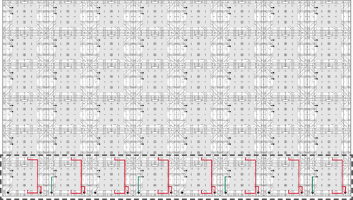
Use the illustration as shown below as a guide to mark the following holes and predrill them.
- At least three mounting holes for the System Control Box.
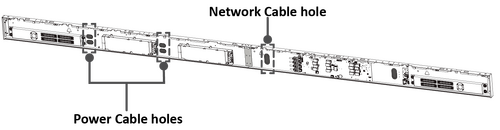
- Four cable access holes, one at the top and three at the bottom. The bottom cable access holes correspond to the holes provided in the System Control Box.
Ensure there is enough space between the mounting holes and cable access holes.
-
 Drill Hole Spacing for System Control Box


Installing the Cabinets
-
Place the Upper Cabinet section "D-1" and Lower Cabinet section "D-2" on stable furniture that can safely support the two Cabinet sections.
Note:- One Cabinet is separated into two sections. Each section weighs around 18.6 kg.
- You can identify Cabinet sections by the labels on the package.
- The arrow marks on each Cabinet section should be pointing up.
-
Attach the Upper and Lower Cabinet sections with the two provided screws (M8 x 20 mm).
-
Carefully lift the assembled Cabinet "D" onto the center of the Upper Wall Mount Brackets.
-
Ensure the Mounting Brackets sit securely on the Wall Mount Brackets as shown below.
-
Repeat Step 1~2 for Cabinet "E".
-
Install the assembled Cabinet "E" on the right side of Cabinet "D" with the provided screws (M8 x 20 mm).
Note: There are 12 screws between each Cabinet. -
Check for unevenness of the Cabinets by rubbing the cross section between each Cabinet. If the cross section is not aligned, loosen the M8 screws slightly and tap the Cabinets until the cross section is flat.
-
Repeat Step 1~2 for the remaining Cabinets and install them onto the Wall Mount Brackets. Start from the center to the right and left sides of the Wall Mount Brackets.
Note: The installation sequence by Cabinet: D ➜ E ➜ C ➜ F ➜ B ➜ G ➜ A ➜ H
Connecting the System Control Box
The left and right sides of the System Control Box are pre-installed with its Covers in the factory. The main system control board is on the right.
The safety wires are used to prevent the Right Cover from falling when accessing the System Control Box. Please ensure that the safety wires are never removed.
Use caution as the System Control Box panel is separated into two pieces with wires attached.
Before installing the System Control Box, the Power and Network Cables of the Cabinets at the lowest row must be routed through the holes provided in the System Control Box from behind.
-
The rubber hole plugs installed on both the System Control Box and Cabinets are used to protect the Cables from rubbing against any pointed edges. Use a knife to cut the hole to size along the cross.
-
 System Control Box (Front View)
-
 Cabinets (Rear View)
-
-
Connect the connector of the longer Power Cable to the power connector of the Cabinet. Then, connect one end of the longer Network Cable to the network port of the Cabinet.
Note:- The longer Power and Network Cables are supplied in the case.
- There are eight Power and four Network Cables to connect.
- Ensure to match the corresponding letters on the Cables to the Cabinets (A to A, B to B, C to C, and so on).
-
After connecting the longer Power and Network Cables, carefully thread them through the holes provided in the Cabinets and run the Cables behind the Cabinets from the top cable access hole through the bottom cable access holes.
Avoid sharp bends in the Cables.
-
Carefully place the System Control Box on stable furniture that can safely support the System Control Box.
-
To open the Right Cover, slowly bring the supplied System Control Box Maintenance Tool near the surface of the Right Cover where the steel plate is located. Then, the Right Cover should detach from the System Control Box magnetically.
DO NOT try to remove or disconnect the safety wires. Please ensure that the safety wires are never removed.
-
Remove the Left Cover by gripping the top edge of the Cover and pulling it toward you. The Left Cover should simply lift away.
-
Secure the System Control Box panel with the Connector Plate using the provided screws (M3 x 6 mm).
-
Further secure the Connector Plate with the two provided screws (M3 x 5 mm).
-
Place the System Control Box accordingly over the drilled mounting holes to attach.
-
Carefully thread the Power and Network Cables through the holes provided in the System Control Box from behind. Ensure to use the correct cable holes for the Power and Network Cables.
Note:- There are three Power and four Network Cables to thread.
- The rubber hole plugs must always be placed in the holes.
-
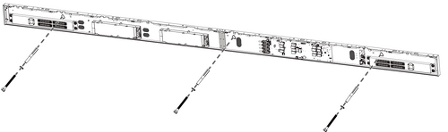
After threading the Power and Network Cables, install the System Control Box onto the wall with the provided screws and lock washers (M8 x 80 mm Expansion for masonry; wood screws for load bearing wood).
-
Remove the pre-installed Power and Network Cables of the Cabinets from the System Control Box.
Note:- There are eight Power and four Network Cables to remove.
- It is recommended to take photos of the completed wiring in the left and main system control boards before removing the Cables.
-
After removing the pre-installed Power and Network Cables of the Cabinets, connect the other end of the longer Network Cable to the network port that was disconnected from the System Control Box in Step 12.
Note: There are four Network Cables to connect. -
After connecting the Network Cables, please follow the diagram below to connect the longer Power Cables to the two AC units of the System Control Box.
DO NOT connect the System Control Box Power Cables at this time.
- Connect the neutral wires (usually white/blue) to the "N1", "N2", and "N" terminals.
- Connect the hot wires (usually black/brown) to the "L1", "L2", and "L" terminals.
- Connect the ground wires (usually in green) to the ground terminals.
The meaning of wiring color may vary by country.
Use the provided wrench to tighten the neutral, hot, and ground conductors in the terminals properly.
-
Connect the two AC units of the System Control Box to the main system control board.
-
Connect the LED Display's left speaker to the Audio Out port.
Note: Ensure that the right speaker is properly connected to the other Audio Out port. -
After the IR Extension Cable is connected, route it through the hole of the System Control Box to the rear.
-
After connecting all Cables and wires, hold the top edge of the Right Cover toward the System Control Box to replace it. Once the Right Cover is replaced, it will be held in place magnetically.
Note: Ensure the Power Button cable is connected before securing the Right Cover. -
Replace the Left Cover by aligning it properly with the System Control Box; then the Left Cover should attach magnetically.
-
Connect the Network Cables (Green) of the Cabinets. Start from the bottom and move to the top.
- Connect the four Network Cables from the System Control Box to Cabinet "B", "D", "F", and "H".
Note: Ensure to match the corresponding letters on the Network Cables to the Cabinets (B to B, D to D, F to F, and H to H).
- Connect the Network Cables of the eight Lower Cabinet sections to their Upper Cabinet sections.
- At the top row, connect the Network Cable of the first Cabinet to the next Cabinet.
Note: There are four Network Cables to connect.
- Connect the four Network Cables from the System Control Box to Cabinet "B", "D", "F", and "H".
-
Connect the Power Cables (Red/Orange) of the Cabinets. Start from the bottom and move to the top.
- Connect the Power Cables from the System Control Box to the eight Cabinets.
Note: Ensure to match the corresponding letters on the Cables to the Cabinets (A to A, B to B, C to C, D to D, and so on).
- Connect the Power Cables of the eight Lower Cabinet sections to their Upper Cabinet sections.
Note: There are eight Power Cables to connect.
- Connect the Power Cables from the System Control Box to the eight Cabinets.
-
Route the Power and Network Cables around the rods provided in the Cabinets and secure the Cables to the rods with the Cable Zip Tie and screw (PM3 x 10 mm). Leave a little slack for later adjustments if needed.


Installing the LED Modules
Please wear Anti-Static Gloves before handling the LED Modules.
To avoid direct contact with the LED Modules, please remove watches, rings, bracelets, or other metal objects.
Use caution when installing the LED Modules.
-
Starting from the LED Module labeled "1" in the top left corner, align each LED Module with the Cabinet, then carefully press the Module into place.
Note: The arrow marks on the back of the LED Modules should be pointing up. -
Attach the remaining LED Modules onto the Cabinets. Install from top left and move to bottom right, ensuring to match the corresponding numbers on the Module to the Cabinet.
Note: Before installing the LED Module, ensure that each Module is flush and that there is little to no gap between each. It may be necessary to gently tap the module to make it flush.
Installing the Screen Bezels
The Screen Bezels' plastic tabs are pre-installed onto the Bezels. Ensure all plastic tabs are properly mounted before installing the Screen Bezels onto the screen.
The label indicates the top of each Screen Bezel. To ensure the Bezels are installed in the correct position, please use the labels on the inside of the Bezels as a guide.
-
Place the Screen Bezel to the correct side of the screen to attach. Start from the left and move to the right.
Note:- Ensure the label side of the Screen Bezel is facing the screen.
- Before installing the Screen Bezels, check the label of each Bezel as the label helps you know which side ("L" = left side & "R" = right side) to attach.
- The illustration below shows the location where each Screen Bezel should be installed.
-
Align the plastic tabs of the Screen Bezel with the holes provided in the screen.
-
Press down on the Screen Bezel until you hear it click into place.
-
Place the remaining Screen Bezel onto the left and right sides of the screen.
-
At the bottom of the screen, loosen the screws securing the pre-installed Screen Bezel and remove it. This provides enough room to the bottom Screen Bezels.
Note:- There are two pre-installed Screen Bezels to remove.
- The pre-installed Screen Bezels come in with two different lengths. Remove the shorter ones.
-
Install the bottom Screen Bezel to the screen with the four provided screws (M3 x10 mm).
Note: There are six bottom Screen Bezels to install.
Turning On the LED Display
-
Make sure the System Control Box Power Cables are connected and plugged into power outlets.
Note: When the System Control Box Power Cables are connected to power outlets, the Power Indicator Light will be a steady red. This means the LED Display is in standby mode. Please refer to the User Guide for more details. -
Your LED Display is now ready to power on.