IFP50-3 Introduction
From ViewSonic Documentation
Package Contents
-
 HDMI Cable (3 m)
 -
 Remote Control
 -
 AAA Battery x 2
 -
 USB Cable (3 m)
 -
 Webcam Plate
 -
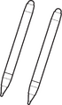 Touch Pen x 2
 -
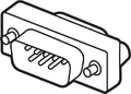 RS-232 Adapter
 -
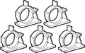 Clamp x 5
 -
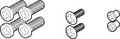 Screw x 8
 -
 Quick Start Guide
 -
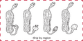 Power Cord


Wall Mount Kit Specifications (VESA)
Please follow the instructions in the wall mount installation guide to install your wall mount or mobile mount bracket. If attaching to other building materials, please contact your nearest dealer.

| Model | VESA Spec. (A x B) | Standard Screw (C x D) | Quantity |
|---|---|---|---|
| IFP5550-3/A/B - 55” | 400 x 200 mm | M8 x 25 mm | 4 |
| IFP6550-3/A/B - 65” | 600 x 400 mm | M8 x 25 mm | 4 |
| IFP7550-3/A/B - 75” | 800 x 400 mm | M8 x 25 mm | 4 |
| IFP8650-3/A/B - 86” | 800 x 600 mm | M8 x 25 mm | 4 |
| IFP9850-3 - 98" | 800 x 600 mm | M8 x 25 mm | 4 |
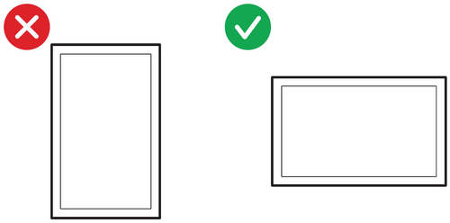
Important:
- Do not use screws that are longer than the standard dimension, as they may cause damage to the inside of the display.
- Only mount the display in landscape orientation. Never mount in a portrait orientation.
Product Overview
Front Panel | Control Panel

Rear Panel

| Number | Description |
|---|---|
| 1 | Power indicator light |
| 2 | Remote control receiver |
| 3 | Turn On/Off the device Tap to enter Energy Saving mode Press and hold for at least two (2) seconds to enter Standby mode |
| 4 | Go to the Home Screen |
| 5 | Return to the previous screen |
| 6 | Enter the Settings menu Press and hold for three (3) seconds to activate Screen Freeze |
| 7 | Decrease the Volume |
| 8 | Increase the Volume |
| 9 | USB 3.0. Smart USB port for PC, HDMI, VGA, and Android input signals. |
| 10 | USB 2.0. Smart USB port for PC, HDMI, VGA, and Android input signals. |
| 11 | Speaker |
| 12 | Subwoofer |
I/O Panel
Lower Right Side

Lower Front Right

Bottom Left

- NOTE:
- TOUCH, HDMI, and VGA are grouped by color; i.e. TOUCH 1 should be used with HDMI 1/2.
- Under the Embedded Player, USB ports only support 2.0 transfer speeds.
| Number | Port | Description |
|---|---|---|
| 1 | USB 3.0 | Connect USB devices such as hard disks, keyboard, mouse, etc. Automatically switches between PC and Android. |
| 2 | TOUCH 1 |
Touch signal output to external PC |
| 3 | HDMI IN 1/2 | High definition input; connect to PC with HDMI output, set-top box, or other video device. |
| 4 | HDMI IN 3 | High definition input; connect to PC with HDMI output, set-top box, or other video device. |
| 5 | TOUCH 2 |
Touch signal output to external PC |
| 6 | Wi-Fi Module Slot | Slot for adding optional Wi-Fi module. |
| 7 | VGA | External computer video input. |
| 8 | AUDIO IN | External computer audio input. |
| 9 | SPDIF | Multichannel sound via optical signals. |
| 10 | RS-232 | Serial interface; used for mutual transfer of data between devices. |
| 11 | AUDIO OUT | Audio output to an external speaker. |
| 12 | LAN | Standard RJ45 (10M/100M/1G for PC; 10M/100M for Android) Internet connection interface. |
| 13 | USB 2.0 | Connect USB devices such as hard disks, keyboard, mouse, etc.
[ 5V dc/0.5A ] |
| 14 | AC Switch | Turn On/Off AC power supply. "I" = Power On; "O" = Power Off |
| 15 | AC IN | AC power input |
Unboxing Video