
VP2786-4K Initial Setup: Difference between revisions
From ViewSonic Documentation
| Line 33: | Line 33: | ||
{{Note-yellow|For use only with a UL certified wall mount kit/bracket. To obtain a wall-mounting kit or height adjustment base, contact ViewSonic® or your local dealer.}} | {{Note-yellow|For use only with a UL certified wall mount kit/bracket. To obtain a wall-mounting kit or height adjustment base, contact ViewSonic® or your local dealer.}} | ||
{| class="wikitable" style="text-align: center;" | {| class="wikitable" style="text-align: center;" width=70% | ||
! style="background-color:#DB0025; color:#ffffff;" | Maximum Loading | ! style="background-color:#DB0025; color:#ffffff;" | Maximum Loading | ||
! style="background-color:#DB0025; color:#ffffff;" | Hole Pattern (W x H) | ! style="background-color:#DB0025; color:#ffffff;" | Hole Pattern<br /> (W x H) | ||
! style="background-color:#DB0025; color:#ffffff;" | Interface Pad (W x H x D) | ! style="background-color:#DB0025; color:#ffffff;" | Interface Pad<br /> (W x H x D) | ||
! style="background-color:#DB0025; color:#ffffff;" | Pad Hole | ! style="background-color:#DB0025; color:#ffffff;" | Pad Hole | ||
! style="background-color:#DB0025; color:#ffffff;" | Screw Specification & Quantity | ! style="background-color:#DB0025; color:#ffffff;" | Screw Specification & Quantity | ||
Revision as of 09:02, 29 December 2022
Stand Installation
- Place the monitor on a flat, stable surface with the screen facing down.
- Align and slide the upper hooks of the monitor stand into the stand mounting slots.
- Lift the device into its upright position on a flat, stable surface.


Always place the device on a flat, stable surface. Failure to do so may cause the device to fall and damage the device and/or result in personal injury.
Wall Mounting
Refer to the table below for the standard dimensions for wall mount kits.
For use only with a UL certified wall mount kit/bracket. To obtain a wall-mounting kit or height adjustment base, contact ViewSonic® or your local dealer.
| Maximum Loading | Hole Pattern (W x H) |
Interface Pad (W x H x D) |
Pad Hole | Screw Specification & Quantity |
|---|---|---|---|---|
| 14 kg | 100 x 100 mm | 115 x 115 x 2.6 mm | Ø 5 mm | M4 x 10 mm - 4 pieces |
- Turn off the device and disconnect all cables.
- Place the device on a flat, stable surface with the screen facing down.
- Pull down slightly to disengage the hooks and remove the stand.
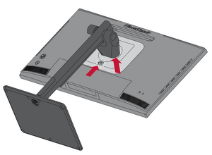
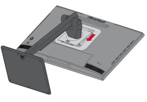
- Attach the mounting bracket to the VESA mounting holes at the rear of the monitor. Then secure it with four (4) screws (M4 x 10 mm).
- Follow the instructions that come with the wall mounting kit to mount the monitor onto the wall.


