
LDP163-181 Dual-Screen Splicing: Difference between revisions
From ViewSonic Documentation
Created page with "<noinclude> {{Sticky_Menu_LDP135-151 |1=LDP163-181_Introduction |2=LDP163-181_Remote_Control |3=LDP163-181_Wall_Installation |4=LDP163-181_Floor_Stand_Installation |5=LDP163-181_Detachable_System_Control_Box |6=LDP163-181_Dual-Screen_Splicing |7=LDP163-181_Portrait_Mode |8=LDP163-181_Connecting_Devices |9=LDP163-181_Using_the_Display |10=LDP163-181_On-Screen_Display_Menu |11=LDP163-181_Embedded_Applications |12=LDP163-181_RS-232_Protocol |13=LDP163-181_Specifications |..." |
No edit summary |
||
| (7 intermediate revisions by the same user not shown) | |||
| Line 1: | Line 1: | ||
<noinclude> | <noinclude> | ||
{{ | {{Sticky_Menu_LDP163-181 | ||
|1=LDP163-181_Introduction | |1=LDP163-181_Introduction | ||
|2=LDP163-181_Remote_Control | |2=LDP163-181_Remote_Control | ||
| Line 7: | Line 7: | ||
|5=LDP163-181_Detachable_System_Control_Box | |5=LDP163-181_Detachable_System_Control_Box | ||
|6=LDP163-181_Dual-Screen_Splicing | |6=LDP163-181_Dual-Screen_Splicing | ||
|7=LDP163- | |7=LDP163-181_Connecting_Devices | ||
|8=LDP163- | |8=LDP163-181_Using_the_Display | ||
|9 | |9=LDP163-181_On-Screen_Display_Menu | ||
|10=LDP163-181_Embedded_Applications | |||
| | |11=LDP163-181_RS-232_Protocol | ||
| | |12=LDP163-181_Specifications | ||
| | |13=LDP163-181_Regulatory_and_Service_Information | ||
| | |||
}} | }} | ||
__TOC__ </noinclude> | __TOC__ </noinclude> | ||
| Line 33: | Line 32: | ||
==Wall Mounting== | ==Wall Mounting== | ||
===Installing the Upper and Lower Wall Mount Brackets=== | ===Installing the Upper and Lower Wall Mount Brackets=== | ||
:<div class="res-img">[[File: | :<div class="res-img">[[File:LDP163-181_DSCB_Wall_Mount_1.png|500px]]</div> | ||
<ol><li>Ensure the wall area and size is an appropriate installation site.</li> | <ol><li>Ensure the wall area and size is an appropriate installation site.</li> | ||
:'''NOTE:''' The height of the Upper ''Wall Mount Brackets'' must not be less than | :'''NOTE:''' The height of the Upper ''Wall Mount Brackets'' must not be less than 102 ²³/₆₄" (2600 mm) from the ground. | ||
<li>Using the ''Wall Mount Bracket'' (pictured above) as a guide, mark at least eight (8) holes and pre-drill them.</li> | <li>Using the ''Wall Mount Bracket'' (pictured above) as a guide, mark at least eight (8) holes and pre-drill them.</li> | ||
<li>Install the first Upper ''Wall Mount Bracket'' with the provided screws (M6x50mm Expansion for masonry; TA6x30mm for load bearing wood).</li> | <li>Install the first Upper ''Wall Mount Bracket'' with the provided screws (M6x50mm Expansion for masonry; TA6x30mm for load bearing wood).</li> | ||
<li>Repeat '''Step 2''', ensuring the second Upper ''Wall Mount Bracket'' is level with the first upper bracket. Keep a 3 ¹¹/₃₂" (85 mm) space between the two brackets.</li> | <li>Repeat '''Step 2''', ensuring the second Upper ''Wall Mount Bracket'' is level with the first upper bracket. Keep a 3 ¹¹/₃₂" (85 mm) space between the two brackets.</li> | ||
<div class="res-img">[[File: | <div class="res-img">[[File:LDP163-181_DSCB_Wall_Mount_2.png|400px]]</div> | ||
<li>Install the Lower ''Wall Mount Brackets'' in the same manner as the Upper ''Wall Mount Brackets''. The distance between the Upper and Lower ''Wall Mount Brackets'' is | <li>Install the Lower ''Wall Mount Brackets'' in the same manner as the Upper ''Wall Mount Brackets''. The distance between the Upper and Lower ''Wall Mount Brackets'' is 66 ²⁷/₆₄" (1687.25 mm).</li> | ||
:'''NOTE:''' You can also install the Upper ''Wall Mount Brackets'', hang the screen, and then install the Lower ''Wall Mount Brackets'' for a more precise fit. | :{| style="vertical-align:middle; width:auto;" | ||
|- | |||
{{ | |style="width:60%;"|<div class="res-img">[[File:LPD163-181_Wall_Mounting_Spacing.png|400px]]</div> | ||
|'''NOTE:''' You can also install the Upper ''Wall Mount Brackets'', hang the screen, and then install the Lower ''Wall Mount Brackets'' for a more precise fit. | |||
<li>Repeat '''Steps 1~5''' for the second display. Keep a | |- | ||
|} | |||
:{| style="vertical-align:middle;" | |||
|- | |||
|{{Icon_Warn}} | |||
|Ensure the wall can safely support 423.29 lbs. (192 kg). | |||
|- | |||
|{{Icon_Warn}} | |||
|Ensure the deviation of wall surface must be < ¹³/₆₄" (< 5 mm). | |||
|- | |||
|} | |||
<li>Repeat '''Steps 1~5''' for the second display. Keep a 5 ³/₈" (136.7 mm) space between the first and second display's ''Wall Mount Brackets''.</li> | |||
<li>After installing both Upper and Lower ''Wall Mount Brackets'' of both displays, the installation wall should look like:</li> | <li>After installing both Upper and Lower ''Wall Mount Brackets'' of both displays, the installation wall should look like:</li> | ||
<div class="res-img">[[File: | <div class="res-img">[[File:LDP163-181_DSS_Wall_Mount_1.png|1000px]]</div> | ||
</ol> | </ol> | ||
===Installing the Cabinets=== | ===Installing the Cabinets=== | ||
<ol><li>Ensure the ''Mounting Brackets'' on the rear of the | <ol> | ||
<div class="res-img">[[File: | <li>Ensure the ''Mounting Brackets'' on the rear of the six (6) ''Cabinets'' are positioned at the top and bottom mounting positions as shown below:</li><br /> | ||
<li>Carefully lift each ''Cabinet'' up onto the Upper ''Wall Mount Brackets'' | |||
<div class="res-img">[[File: | <div class="res-img">[[File:LDP163-181_Rear_Panels_Separate.png|500px]]</div><br /> | ||
<li>Ensure the ''Mounting Brackets'' sit securely on the ''Wall Mount Brackets'' as shown below.</li> | |||
<div class="res-img">[[File: | <li>Carefully lift each ''Cabinet'' up onto the Upper ''Wall Mount Brackets'' starting from the left.</li><br /> | ||
<li>Push each ''Locking Bolt'' and lock each ''Hook'' with the hex tool to securely connect each cabinet together. It may be necessary to align the hole with | |||
:'''NOTE:''' There are | <div class="res-img">[[File:LDP163-181_Wall_Mounting_After_One_Screen.png|500px]]</div><br /> | ||
<li>Ensure the ''Mounting Brackets'' sit securely on the ''Wall Mount Brackets'' as shown below.</li><br /> | |||
<div class="res-img">[[File:LD_Wall_Mount_Close_Up.svg|400px]]</div><br /> | |||
<li>Push each ''Locking Bolt'' and lock each ''Hook'' with the hex tool to securely connect each cabinet together. It may be necessary to align the hole with the hex tool in order to engage the ''Locking Bolt''.</li><br /> | |||
<div class="res-img">[[File:LDP163-181_Wall_Mounting_Connecting_Screens.png|500px]]</div><br /> | |||
:'''NOTE:''' There are six (6) ''Locking Bolts'' and 12 ''Hooks'' between each cabinet. | |||
<li>Place the remaining ''Cabinets'' up onto the Upper ''Wall Mount Brackets''. Install from left to right, ensuring the ''Mounting Brackets'' sit securely on the ''Wall Mount Brackets''.</li> | <li>Place the remaining ''Cabinets'' up onto the Upper ''Wall Mount Brackets''. Install from left to right, ensuring the ''Mounting Brackets'' sit securely on the ''Wall Mount Brackets''.</li> | ||
<li>Repeat '''Step 4''', securing the ''Cabinets'' together with each ''Locking Bolt'' and ''Hook''.</li> | |||
:'''NOTE:''' There are | <li>Repeat '''Step 4''', securing the ''Cabinets'' together with each ''Locking Bolt'' and ''Hook''.</li><br /> | ||
<div class="res-img">[[File: | |||
<div class="res-img">[[File:LDP163-181_Wall_Mounting_All_Screens.png|500px]]</div> | |||
:'''NOTE:''' There are six (6) ''Locking Bolts'' and 12 ''Hooks'' between each cabinet. | |||
<li>Remove the screws and bezel from ''Cabinet #6'' and ''Cabinet #7''.</li> | |||
<div class="res-img">[[File:LDP163-181_DSS_Close_Up.png|400px]]</div> | |||
<li>Repeat '''Steps 1~6''' for the second display.</li> | <li>Repeat '''Steps 1~6''' for the second display.</li> | ||
<li>After installing the Cabinets of both displays, the installation wall should look like:</li> | <li>After installing the Cabinets of both displays, the installation wall should look like:</li> | ||
<div class="res-img">[[File: | <div class="res-img">[[File:LDP163-181_DSS_Install_Cabinet_1.png|1000px]]</div> | ||
</ol> | </ol> | ||
===Connecting the System Control Box (Standard Installation)=== | ===Connecting the System Control Box (Standard Installation)=== | ||
<ol><li>Carefully unfold the ''System Control Box'' panel. Ensure the main system control board is on the right.</li> | <ol> | ||
:'''NOTE:''' Use caution as the ''System Control Box'' panel | <li>Carefully unfold the ''System Control Box'' panel. Ensure the main system control board is on the right.</li> | ||
<li> | |||
<div class="res-img">[[File: | :'''NOTE:''' Use caution as the ''System Control Box'' panel will be separated into two pieces, however the wires are connected. | ||
<li>You can also reroute the power cable for cable management. Loosen the two (2) PWM 4x6mm screws, pull the power cable out, thread the power cable through the hole and then fasten the screws tightly.</li> | |||
<div class="res-img">[[File:LDP135- | <li>Align the holes of the ''Cabinet'' with the ''System Control Box'' to attach.</li><br /> | ||
<li>Further secure the ''System Control Box'' to the ''Cabinets'' with the 20 provided M6x10mm | <div class="res-img">[[File:LDP163-181_Wall_Mounting_Connecting_Box.png|550px]]</div><br /> | ||
<div class="res-img">[[File: | |||
<li>You can also reroute the power cable at two positions for cable management. Loosen the two (2) PWM 4x6mm screws, pull the power cable out, thread the power cable through the hole and then fasten the screws tightly.</li><br /> | |||
<div class="res-img">[[File:LDP135-151_Control_Box_Cable_mangement.png|500px]]</div><br /> | |||
<li>Further secure the ''System Control Box'' to the ''Cabinets'' with the 20 provided screws (M6x10mm).</li><br /> | |||
<div class="res-img">[[File:LD_Box_Install.png|400px]]</div><br /> | |||
<li>Connect the Network and Power cables of the ''Cabinets'' to the ''System Control Box''.</li> | <li>Connect the Network and Power cables of the ''Cabinets'' to the ''System Control Box''.</li> | ||
:'''NOTE:''' There are | |||
<div class="res-img">[[File: | :'''NOTE:''' There are six (6) Network and six (6) Power cables to connect. | ||
<br /> | |||
<div class="res-img">[[File:LDP163-181_Wall_Mounting_Connecting_Net_Pow.png|550px]]</div> | |||
<li>Repeat '''Steps 1~5''' for the second display.</li> | <li>Repeat '''Steps 1~5''' for the second display.</li> | ||
<li>After installing the System Control Box of both displays, the installation wall should look like:</li> | <li>After installing the System Control Box of both displays, the installation wall should look like:</li> | ||
<div class="res-img">[[File: | <div class="res-img">[[File:LDP163-181_DSS_SCB_Install_Standard_5.png|600px]]</div> | ||
<li>Connect one end of an HDMI cable to the '''HDMI OUT''' port of Display 2. Then, connect the other end of the cable to the '''HDMI IN''' port of Display 1.</li> | <li>Connect one end of an HDMI cable to the '''HDMI OUT''' port of Display 2. Then, connect the other end of the cable to the '''HDMI IN''' port of Display 1.</li> | ||
<div class="res-img">[[File:LDP135-151_DSS_SCB_Install_Standard_6.png|800px]]</div> | <div class="res-img">[[File:LDP135-151_DSS_SCB_Install_Standard_6.png|800px]]</div> | ||
| Line 90: | Line 126: | ||
<div class="res-img">[[File:LDP135-151_DSS_SCB_Install_Standard_7.png|400px]]</div> | <div class="res-img">[[File:LDP135-151_DSS_SCB_Install_Standard_7.png|400px]]</div> | ||
<li>Install the ''System Control Box Covers'' with the KM3x6mm screws from left to right (i.e., Display 1 left cover, Display 1 middle cover, Display 1 right cover, Display 2 left cover, etc.).</li> | <li>Install the ''System Control Box Covers'' with the KM3x6mm screws from left to right (i.e., Display 1 left cover, Display 1 middle cover, Display 1 right cover, Display 2 left cover, etc.).</li> | ||
:'''NOTE:''' See [[ | :'''NOTE:''' See [[LDP163-181_Wall_Installation#Installing_System_Control_Box_Covers|Installing System Control Box Covers]] for more information.</ol> | ||
===Connecting the System Control Box (Hidden Installation)=== | ===Connecting the System Control Box (Hidden Installation)=== | ||
| Line 104: | Line 140: | ||
:<div class="res-img">[[File:LDP135-151_DSCB_Install_2.png|400px]]</div> | :<div class="res-img">[[File:LDP135-151_DSCB_Install_2.png|400px]]</div> | ||
<li>Connect the Network and Power cables of the ''Cabinets'' to the ''System Control Box''.</li> | <li>Connect the Network and Power cables of the ''Cabinets'' to the ''System Control Box''.</li> | ||
:'''NOTE:''' There are | :'''NOTE:''' There are six (6) Network and six (6) Power cables to connect. | ||
* Route the Power cable through the opening provided in the ''Cabinet'' and connect it to the power plug. | * Route the Power cable through the opening provided in the ''Cabinet'' and connect it to the power plug. | ||
:<div class="res-img">[[File:LDP135-151_DSCB_Net_Power_1.png]]</div> | :<div class="res-img">[[File:LDP135-151_DSCB_Net_Power_1.png]]</div> | ||
| Line 113: | Line 149: | ||
===Installing the LED Modules=== | ===Installing the LED Modules=== | ||
{{ | Install each ''LED Module'' onto the ''Cabinets'', being sure to match the corresponding numbers on the ''Module'' to the ''Cabinet''. | ||
{| style="vertical-align:middle;" | |||
|- | |||
|{{Icon_Warn}} | |||
|Please wear Anti-Static Gloves before installing the LED modules. | |||
|- | |||
|} | |||
<ol><li>Starting with Display 1, install each ''LED Module'' onto the ''Cabinets'', being sure to match the corresponding numbers on the ''Module'' to the ''Cabinet''.</li> | <ol><li>Starting with Display 1, install each ''LED Module'' onto the ''Cabinets'', being sure to match the corresponding numbers on the ''Module'' to the ''Cabinet''.</li> | ||
<div class="res-img">[[File: | <div class="res-img">[[File:LDP163-181_Wall_Mounting_Modules_1.png|500px]]</div> | ||
<li>Ensure each ''Module'' is flush and that there is little to no gap between each. It may be necessary to gently tap the module to make it flush.</li> | <li>Ensure each ''Module'' is flush and that there is little to no gap between each. It may be necessary to gently tap the module to make it flush.</li> | ||
<div class="res-img">[[File: | <div class="res-img">[[File:LDP108-121_Wall_Mounting_Modules_No_Cover.png|500px]]</div> | ||
<li>Once Display 1 is complete, repeat '''Steps 1~2''' for Display 2.</li> | <li>Once Display 1 is complete, repeat '''Steps 1~2''' for Display 2.</li> | ||
<li>After installing the ''LED Modules'' of both displays, the installation wall should look like:</li> | <li>After installing the ''LED Modules'' of both displays, the installation wall should look like:</li> | ||
{| | {| | ||
|- | |- | ||
| <div class="res-img">[[File: | | <div class="res-img">[[File:LDP163-181_DSS_1.png]]</div> | ||
|- style="font-weight:bold;" | |- | ||
| Standard Installation | | style="font-weight:bold;"|Standard Installation | ||
|- | |- | ||
| <div class="res-img">[[File: | | <div class="res-img">[[File:LDP163-181_DSS_2.png]]</div> | ||
|- style="font-weight:bold;" | |- | ||
| Hidden System Control Box Installation | | style="font-weight:bold;"|Hidden System Control Box Installation | ||
|} | |} | ||
</ol> | </ol> | ||
Latest revision as of 10:05, 2 August 2023
Dual-Screen Splicing
Two (2) DirectView LED Displays can be installed together to create one (1) large display.
 |
| Standard Installation |
 |
| Hidden System Control Box Installation |
- NOTE: The System Control Boxes can be installed under the Cabinets (standard installation) for front access, or behind the Cabinets.
Wall Mounting
Installing the Upper and Lower Wall Mount Brackets

- Ensure the wall area and size is an appropriate installation site.
- NOTE: The height of the Upper Wall Mount Brackets must not be less than 102 ²³/₆₄" (2600 mm) from the ground.
- Using the Wall Mount Bracket (pictured above) as a guide, mark at least eight (8) holes and pre-drill them.
- Install the first Upper Wall Mount Bracket with the provided screws (M6x50mm Expansion for masonry; TA6x30mm for load bearing wood).
- Repeat Step 2, ensuring the second Upper Wall Mount Bracket is level with the first upper bracket. Keep a 3 ¹¹/₃₂" (85 mm) space between the two brackets.
- Install the Lower Wall Mount Brackets in the same manner as the Upper Wall Mount Brackets. The distance between the Upper and Lower Wall Mount Brackets is 66 ²⁷/₆₄" (1687.25 mm).

NOTE: You can also install the Upper Wall Mount Brackets, hang the screen, and then install the Lower Wall Mount Brackets for a more precise fit. 
Ensure the wall can safely support 423.29 lbs. (192 kg). Ensure the deviation of wall surface must be < ¹³/₆₄" (< 5 mm). - Repeat Steps 1~5 for the second display. Keep a 5 ³/₈" (136.7 mm) space between the first and second display's Wall Mount Brackets.
- After installing both Upper and Lower Wall Mount Brackets of both displays, the installation wall should look like:


Installing the Cabinets
- Ensure the Mounting Brackets on the rear of the six (6) Cabinets are positioned at the top and bottom mounting positions as shown below:
- Carefully lift each Cabinet up onto the Upper Wall Mount Brackets starting from the left.
- Ensure the Mounting Brackets sit securely on the Wall Mount Brackets as shown below.
- Push each Locking Bolt and lock each Hook with the hex tool to securely connect each cabinet together. It may be necessary to align the hole with the hex tool in order to engage the Locking Bolt.
- NOTE: There are six (6) Locking Bolts and 12 Hooks between each cabinet.
- Place the remaining Cabinets up onto the Upper Wall Mount Brackets. Install from left to right, ensuring the Mounting Brackets sit securely on the Wall Mount Brackets.
- Repeat Step 4, securing the Cabinets together with each Locking Bolt and Hook.
- NOTE: There are six (6) Locking Bolts and 12 Hooks between each cabinet.
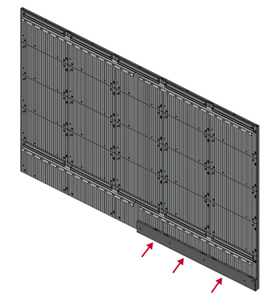
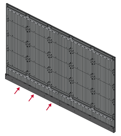
- Remove the screws and bezel from Cabinet #6 and Cabinet #7.
- Repeat Steps 1~6 for the second display.
- After installing the Cabinets of both displays, the installation wall should look like:


Connecting the System Control Box (Standard Installation)
- Carefully unfold the System Control Box panel. Ensure the main system control board is on the right.
- NOTE: Use caution as the System Control Box panel will be separated into two pieces, however the wires are connected.
- Align the holes of the Cabinet with the System Control Box to attach.
- You can also reroute the power cable at two positions for cable management. Loosen the two (2) PWM 4x6mm screws, pull the power cable out, thread the power cable through the hole and then fasten the screws tightly.
- Further secure the System Control Box to the Cabinets with the 20 provided screws (M6x10mm).
- Connect the Network and Power cables of the Cabinets to the System Control Box.
- NOTE: There are six (6) Network and six (6) Power cables to connect.
- Repeat Steps 1~5 for the second display.
- After installing the System Control Box of both displays, the installation wall should look like:
- Connect one end of an HDMI cable to the HDMI OUT port of Display 2. Then, connect the other end of the cable to the HDMI IN port of Display 1.
- NOTE: Route the HDMI cable as shown below:
- Install the System Control Box Covers with the KM3x6mm screws from left to right (i.e., Display 1 left cover, Display 1 middle cover, Display 1 right cover, Display 2 left cover, etc.).
- NOTE: See Installing System Control Box Covers for more information.


Connecting the System Control Box (Hidden Installation)
- Connect one end of an HDMI cable to the HDMI OUT port of Display 2. Then, connect the other end of the cable to the HDMI IN port of Display 1.
- NOTE: Route the HDMI cable as shown below:
- Carefully unfold the System Control Box panel. Ensure the main system control board is on the right.
- NOTE: Use caution as the System Control Box panel is separated into two pieces with wires attached.
- Install the left part of System Control Box using the M6x16mm screws behind the Cabinet.
- Install the right part of the System Control Box using the M6x16mm screws behind the Cabinet.
- Connect the Network and Power cables of the Cabinets to the System Control Box.
- NOTE: There are six (6) Network and six (6) Power cables to connect.
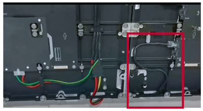
- Route the Power cable through the opening provided in the Cabinet and connect it to the power plug.
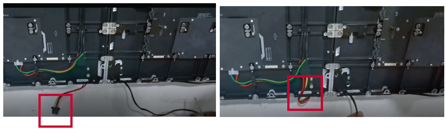
- Route the Network cable through the opening provided in the Cabinet into an “S-shape" and connect it to the network port.
- Repeat Steps 1~4 for the second display.
- Install the bezels from the bottom of the screen and use the M6x10mm screws to secure it to the Cabinet.


Installing the LED Modules
Install each LED Module onto the Cabinets, being sure to match the corresponding numbers on the Module to the Cabinet.
 |
Please wear Anti-Static Gloves before installing the LED modules. |
- Starting with Display 1, install each LED Module onto the Cabinets, being sure to match the corresponding numbers on the Module to the Cabinet.
- Ensure each Module is flush and that there is little to no gap between each. It may be necessary to gently tap the module to make it flush.
- Once Display 1 is complete, repeat Steps 1~2 for Display 2.
- After installing the LED Modules of both displays, the installation wall should look like:


 |
| Standard Installation |
 |
| Hidden System Control Box Installation |