LDP163-181 Floor Stand Installation
From ViewSonic Documentation
Before Installation

Maintain an adequate air gap between the back of the display and any wall for proper ventilation. Ensure there is no direct airflow from air conditioning or heating vents blowing on the display. Avoid installing the display in places with high humidity. Due to high power usage, always use power cords specifically designed for this product.
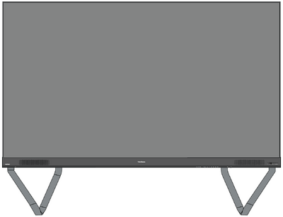
Floor Stand Installation
The floor stand is an optional accessory. Follow the below instructions to install your LED Display onto the stand.
Component List
| Letter | Item | Quantity | Description |
|---|---|---|---|
| A | 1 | Hex Tool | |
| B | 8 | M6 x 80mm Bolt | |
| C |  |
1 | Left Support |
| D |  |
1 | Bottom Cross Beam |
| E |  |
1 | Right Support |
| F |  |
1 | Top Cross Beam |
Dimensions

Constructing the Floor Stand

- Connect the Left Support to the Bottom Cross Beam with two (2) M6 x 80mm bolts.
- Connect the Right Support with the Bottom Cross Beam with two (2) M6 x 80mm bolts.
- Connect the Top Cross Beam to the Left and Right Supports with four (4) M6 x 80mm bolts.
- NOTE: Ensure the groove of the Top Cross Beam faces inwards.
- Ensure all bolts are tightened properly.
Connecting the System Control Box to the Floor Stand
- Carefully unfold the System Control Box panel. Ensure the main system control board is on the left.
- NOTE: Use caution as the System Control Box panel will be separated into two pieces, however the wires are connected.
- Align the System Control Box to the eight (8) holes on the Bottom Cross Beam and secure it with eight (8) screws (M6x10mm).
- Install two (2) additional screws (M6x10mm) to connect the two halves of the System Control Box.


Installing the Middle Cabinets
- Ensure the four (4) Mounting Brackets on the rear of the four (4) Middle Cabinets are positioned as shown below:
- Carefully lift a Cabinet up onto the Floor Stand, securing the Mounting Bracket into the support channel of the Top Cross Beam. The bottom of the Cabinet will rest on the Bottom Cross Beam.
- Secure the Cabinet to the Support with the provided screws (M6x10mm).
- Push each Locking Bolt and lock each Hook with the hex tool to securely connect each cabinet together.
- NOTE: There are six (6) Locking Bolts and 12 Hooks between each cabinet.
- Repeat Steps 2~4 for the remaining Middle Cabinets.


Installing the Left and Right Cabinet
- Carefully lift the Left and Right Cabinet up onto the Floor Stand, securing the Mounting Bracket into the support channel of the Top Cross Beam. The bottom of the Cabinet will rest on the Bottom Cross Beam.
- NOTE: Ensure the holes of the Cabinet and the System Control Box are aligned.
- Push each Locking Bolt and lock each Hook with the hex tool to securely connect the Left and Right Cabinet to the Middle Cabinets.
- NOTE: There are six (6) Locking Bolts and 12 Hooks between each cabinet.

Connecting the Network and Power Cables
Connect the Network and Power cables of each Cabinet to the System Control Box.
- NOTE: There are six (6) Network and six (6) Power cables to connect.


Installing the LED Modules
Install each LED Module onto the Cabinets, being sure to match the corresponding numbers on the Module to the Cabinet. Ensure each Module is flush and that there is little to no gap between each.
| Please wear Anti-Static Gloves before installing the LED modules. |

Installing System Control Box Covers
There are three (3) System Control Box Covers: Left, Middle, and Right.

- Begin by installing the Right Cover onto the System Control Box.
- NOTE: Ensure the Power Button cable is connected to the System Control Box Power cable before securing the Cover.
- After connecting the Power Button cable, ensure the Right Cover is properly aligned with the System Control Box; then secure it with the 12 provided screws (KM3x6mm).
- Repeat the above steps for the Middle and Left Cover. Once all of the Covers are secured, your LED Display is ready to use.