LD135-152 Flight Case Unboxing
From ViewSonic Documentation
Unboxing the Flight Case
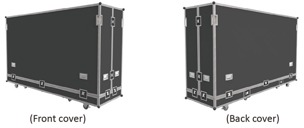
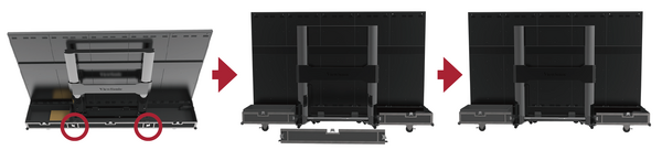
- After the flight case is moved to the designated location, open the flight case according to the sequence of Front cover, Back cover, Movable plate and Bottom plate in turn. To distinguish the Front cover and Back cover, refer to the following diagram.
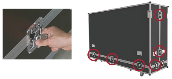
- As shown below, pull the handle of the lock-ups, and rotate the handle counterclockwise to unlock those 9 lock-ups connecting the Front cover with the Bottom plate and the Back cover, ensuring that each lock-up will not be interlocked.
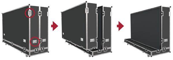
- Two people will need to grip the handles, as indicated by the red circles below, and pull. While lifting, keep the the Front cover level as it is moved to another location.
- As shown below, pull the handle of the lock-ups, and rotate the handle counterclockwise to unlock those 5 lock-ups connecting the Back cover with the Bottom plate, ensuring that each lock-up will not be interlocked. Two people will need to grip the handles, as indicated by the red circles below, and pull. While lifting, lift off the Back cover to another location, ensuring to keep the cover level.
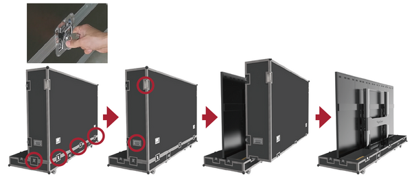
- As shown in the red circles below, open the 4 lock-ups of the Movable plate at the bottom of the flight case, and lift the Movable plate while holding up the bottom of it. Pull out the Movable plate from behind to separate.
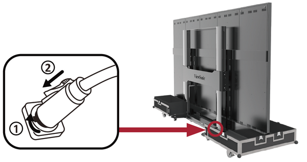
- Take the power cord out of the accessory box. Insert the flight plug into the female socket at the right of the base control box of the screen and rotate the plug 90° clockwise (as shown below). Ensure the plug is connected securely (a click should be heard). Insert the other end of the plug into a power socket. Ensure that the power socket meets the specifications and standards of the LED display screen (30A socket for 110V area, and 16A socket for 220V area).
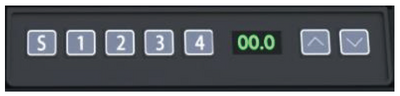
- After the power cord is properly connected, the green light and digits on the control lifting plate of the base of the screen will be ON. Keys are used to control the lifting operations of the screen.
- After the screen is lifted to a certain height, pull out the Bottom plate of the flight case from the front.


