IFP52-1C Introduction: Difference between revisions
From ViewSonic Documentation
| Line 110: | Line 110: | ||
===I/O Panels=== | ===I/O Panels=== | ||
<div class="res-img">[[File:IFP52-1C_IO.png|IFP52-1C I/O Panel| | <div class="res-img">[[File:IFP52-1C_IO.png|IFP52-1C I/O Panel|700px]]</div> | ||
{| class="wikitable" style="text-align:center;" width=50% | {| class="wikitable" style="text-align:center;" width=50% | ||
Revision as of 06:25, 14 September 2021
Package Contents
-
 HDMI Cable (10 ft/3 m)
 -
 Power Cable
(ship by region) -
 Remote Control
 -
 AAA Battery x 2
 -
 USB Cable for Touch (10 ft/3 m)
 -
 Webcam Plate
 -
 Webcam Screws x 4 (M4x6mm x 2; M3x6mm x 2)
 -
 Compliance Statement
 -
 Touch Pen x 2
 -
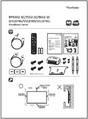 Quick Start Guide
 -
 RS-232 Adapter
 -
 Clamp x 5
 -
 USB Type-C Cable (5.9 ft/1.8 m)
 -
 Eraser
 -
 Wall Mount Screws x 4 (M8x25mm x4)


Wall Mount Kit Specifications (VESA)
Please follow the instructions in the wall mount installation guide to install your wall mount or mobile mount bracket. If attaching to other building materials, please contact your nearest dealer.

| Model | VESA Spec. (A x B) | Standard Screw (C x D) | Quantity |
|---|---|---|---|
| IFP6552-1C Series - 65” | 600 x 400 mm | M8 x 25 mm | 4 |
| IFP7552-1C Series - 75” | 800 x 400 mm | M8 x 25 mm | 4 |
| IFP8652-1C Series - 86” | 800 x 600 mm | M8 x 25 mm | 4 |
Do not use screws that are longer than the standard dimension, as they may cause damage to the inside of the display.
Product Overview
Front Panel

Rear Panel

Control Panel

| Number | Description |
|---|---|
| 1 | Ambient Light Sensor to monitor the ambient light |
| 2 | Remote control receiver |
| 3 |
|
| 4 | Back to the ViewBoard player’s main interface |
| 5 | Return to the ViewBoard player’s previous level |
| 6 | Disable/enable the touch screen |
| 7 | Freeze the current image on the screen |
| 8 | Dncrease the Volume |
| 9 | Increase the Volume |
I/O Panels

| Number | Port | Description |
|---|---|---|
| 1 | USB 3.0 | Connect USB devices such as hard disks, keyboard, mouse, etc. Automatically switches between PC and Android. |
| 2 | TOUCH 1 |
Touch signal output to external PC |
| 3 | HDMI IN 1/2 | High definition input; connect to PC with HDMI output, set-top box, or other video device. |
| 4 | HDMI IN 3 | High definition input; connect to PC with HDMI output, set-top box, or other video device. |
| 5 | TOUCH 2 |
Touch signal output to external PC |
| 6 | Wi-Fi Module Slot | Slot for adding optional Wi-Fi module. |
| 7 | VGA | External computer video input. |
| 8 | AUDIO IN | External computer audio input. |
| 9 | SPDIF | Multichannel sound via optical signals. |
| 10 | RS-232 | Serial interface; used for mutual transfer of data between devices. |
| 11 | AUDIO OUT | Audio output to an external speaker. |
| 12 | LAN | Standard RJ45 (10M/100M/1G for PC; 10M/100M for Android) Internet connection interface. |
| 13 | USB 2.0 | Connect USB devices such as hard disks, keyboard, mouse, etc.
[ 5V dc/0.5A ] |
| 14 | AC Switch | Turn On/Off AC power supply. "I" = Power On; "O" = Power Off |
| 15 | AC IN | AC power input |