
LDC031 Wall Installation: Difference between revisions
// via Wikitext Extension for VSCode |
No edit summary |
||
| (44 intermediate revisions by one other user not shown) | |||
| Line 22: | Line 22: | ||
</div> | </div> | ||
</div> | </div> | ||
</noinclude> | |||
=Wall Installation= | =Wall Installation= | ||
==Introduction== | ==Introduction== | ||
| Line 34: | Line 33: | ||
<p><i class='fas fa-exclamation-circle' style='font-size:24px'></i> Due to high power usage, always use power cords specifically designed for this product.</p> | <p><i class='fas fa-exclamation-circle' style='font-size:24px'></i> Due to high power usage, always use power cords specifically designed for this product.</p> | ||
<p><i class='fas fa-exclamation-circle' style='font-size:24px'></i> Wood may split if holes are not pre-drilled before installing the Wall Mount Brackets.</p> | <p><i class='fas fa-exclamation-circle' style='font-size:24px'></i> Wood may split if holes are not pre-drilled before installing the Wall Mount Brackets.</p> | ||
<p><i class='fas fa-exclamation-circle' style='font-size:24px'></i> Ensure the deviation of the wall surface is < 5 mm.</p> | <p><i class='fas fa-exclamation-circle' style='font-size:24px'></i> Ensure the deviation of the wall surface is < 5 mm.</p> | ||
<p><i class='fas fa-exclamation-circle' style='font-size:24px'></i> Wear protective gear, such as gloves and protective shoes, when handling the LED Display.</p> | <p><i class='fas fa-exclamation-circle' style='font-size:24px'></i> Wear protective gear, such as gloves and protective shoes, when handling the LED Display.</p> | ||
<p><i class='fas fa-exclamation-circle' style='font-size:24px'></i> Due to the size and weight, it is recommended that two or more people handle it.</p> | <p><i class='fas fa-exclamation-circle' style='font-size:24px'></i> Due to the size and weight, it is recommended that two or more people handle it.</p> | ||
==Standard Installation== | ==Standard Installation== | ||
You can find all appendixes at the end of the Installation Guide in the package. | |||
===Wall Mounting=== | ===Wall Mounting=== | ||
Before the installation, please ensure the supplied Wall Mount Brackets match the ones illustrated in the Appendix A | Before the installation, please ensure the supplied Wall Mount Brackets match the ones illustrated in the Appendix A. | ||
<ol> | <ol> | ||
<li> | <li> | ||
| Line 49: | Line 50: | ||
*The installation type. | *The installation type. | ||
*Cable pathways between the Cabinets, and between the Cabinets and System Control Box.</p> | *Cable pathways between the Cabinets, and between the Cabinets and System Control Box.</p> | ||
{{Note| | {{Note|Refer to the included Appendix A for the detailed instructions on mounting the Wall Mount Brackets, including minimum space requirements.}} | ||
</li> | </li> | ||
| Line 73: | Line 74: | ||
===Installing the Cabinets=== | ===Installing the Cabinets=== | ||
<p>Before installing the Cabinets on the Wall Mount Brackets, it is recommended to refer to the wiring diagram provided in Appendix B first to decide how you want to route the Cables for the power and network connections to the Cabinets | <p>Before installing the Cabinets on the Wall Mount Brackets, it is recommended to refer to the wiring diagram provided in the included Appendix B first to decide how you want to route the Cables for the power and network connections to the Cabinets.</p> | ||
<p>Additionally, the rubber hole plugs installed on the Cabinets are used to protect the Power and Network Cables from rubbing against any pointed edges. After installing all Cabinets, use a knife to cut the rubber hole plugs to size along the cross according to the thickness of the Cables.</p> | <p>Additionally, the rubber hole plugs installed on the Cabinets are used to protect the Power and Network Cables from rubbing against any pointed edges. After installing all Cabinets, use a knife to cut the rubber hole plugs to size along the cross according to the thickness of the Cables.</p> | ||
{{Note|You can find Appendix B at the end of the Installation Guide in the package.}} | |||
<ol> | <ol> | ||
<li>Place each section of the Cabinet on stable furniture that can safely support them. Start with the Cabinets from the center, then move to the right and left sides of the Wall Mount Brackets (see the | <li>Place each section of the Cabinet on stable furniture that can safely support them. Start with the Cabinets from the center, then move to the right and left sides of the Wall Mount Brackets (see the included Appendix B to identify Cabinet sections and installation sequence). | ||
{{Note| | {{Note| | ||
:*One Cabinet is divided into separate sections. You can identify these Cabinet sections by the labels on each section or the package. | :*One Cabinet is divided into separate sections. You can identify these Cabinet sections by the labels on each section or the package. | ||
| Line 103: | Line 105: | ||
<li> | <li> | ||
<p>Check for unevenness of the Cabinets by rubbing the cross section between each Cabinet. If the cross section is not aligned, loosen the M8 screws slightly and tap the Cabinets until the cross section is flat.</p> | <p>Check for unevenness of the Cabinets by rubbing the cross section between each Cabinet. If the cross section is not aligned, loosen the M8 screws slightly and tap the Cabinets until the cross section is flat.</p> | ||
<div class="res-img">[[File: | <div class="res-img">[[File:LDC031 Installing Cabinets-7.png|300px|alt=the cross sections between each Cabinet]]</div> | ||
</li> | </li> | ||
<li> | <li> | ||
<p>Repeat '''Step 1~7''' for the remaining Cabinets, ensuring that the Mounting Brackets sit securely on the Wall Mount Brackets, and that the Cabinets are properly secured together.</p> | <p>Repeat '''Step 1~7''' for the remaining Cabinets, ensuring that the Mounting Brackets sit securely on the Wall Mount Brackets, and that the Cabinets are properly secured together.</p> | ||
{{Note|Refer to the | {{Note|Refer to the included Appendix B to identify the Cabinets and installation sequence.}} | ||
</li> | </li> | ||
<li>After installing all Cabinets, cut the rubber hole plugs to size along the cross with a knife (see the | <li>After installing all Cabinets, cut the rubber hole plugs to size along the cross with a knife (see the included Appendix B for the position of the hole plugs).</li> | ||
</ol> | </ol> | ||
===Connecting the System Control Box=== | ===Connecting and Installing the System Control Box=== | ||
The left and right sides of the System Control Box are pre-installed with its Covers in the factory. The main system control board is on the right. | The left and right sides of the System Control Box are pre-installed with its Covers in the factory. The main system control board is on the right. | ||
| Line 125: | Line 127: | ||
width:auto; | width:auto; | ||
max-width:70%; | max-width:70%; | ||
"><p><i class='fas fa-exclamation-circle' style='font-size:24px'></i> The safety wires are used to prevent the Right Cover from falling when accessing the System Control Box. Please ensure that the safety wires are never removed.</p><p><i class='fas fa-exclamation-circle' style='font-size:24px'></i> Use caution as the System Control Box panel is separated into two pieces with wires attached (See the | "><p><i class='fas fa-exclamation-circle' style='font-size:24px'></i> The safety wires are used to prevent the Right Cover from falling when accessing the System Control Box. Please ensure that the safety wires are never removed.</p><p><i class='fas fa-exclamation-circle' style='font-size:24px'></i> Use caution as the System Control Box panel is separated into two pieces with wires attached (See the included Appendix B for example system wiring diagrams).</p> | ||
<div class="res-img">[[File:LDM231-251 SCB Overview.png|600px|alt=System Control Box Overview]]</div> | <div class="res-img">[[File:LDM231-251 SCB Overview.png|600px|alt=System Control Box Overview]]</div> | ||
| Line 146: | Line 148: | ||
max-width:70%; | max-width:70%; | ||
"><p><i class='fas fa-exclamation-circle' style='font-size:24px'></i> DO NOT try to remove or disconnect the safety wires. Please ensure that the safety wires are never removed.</p></div> | "><p><i class='fas fa-exclamation-circle' style='font-size:24px'></i> DO NOT try to remove or disconnect the safety wires. Please ensure that the safety wires are never removed.</p></div> | ||
<div class="res-img">[[File:LDC031 Connecting SCB-2.png |450px|alt=Removing the Right System Control Box Cover]]</div> | <div class="res-img">[[File:LDC031 Connecting SCB-2-1.png |450px|The '''LD-SCB-011/LD-SCB-021''' control box|alt=Removing the Right System Control Box Cover]]</div> | ||
</li> | </li> | ||
| Line 166: | Line 168: | ||
<li> | <li> | ||
<p>Install the System Control Box to the bottom of the Cabinets with the provided screws (M8 x 20 mm).</p> | <p>Install the System Control Box to the bottom of the Cabinets with the provided screws (M8 x 20 mm).</p> | ||
<div class="res-img">[[File:LDM231-251 Connecting SCB-8.png |500px|alt=Installing SCB]]</div> | |||
<div class="res-img">[[File: | |||
</li> | </li> | ||
<li> | <li> | ||
<p>Connect the Power and Network Cables from the System Control Box to each Cabinet. Start from the bottom and move to the top (see the | <p>Connect the Power and Network Cables from the System Control Box to each Cabinet. Start from the bottom and move to the top (see the included Appendix B for example system wiring diagrams, including wire colors and connection points).</p> | ||
{{Note|Ensure to match the corresponding letters on the Cables to the Cabinets (A to A, B to B, C to C, D to D, and so on).}} | {{Note|Ensure to match the corresponding letters on the Cables to the Cabinets (A to A, B to B, C to C, D to D, and so on).}} | ||
</li> | </li> | ||
| Line 193: | Line 194: | ||
width:auto; | width:auto; | ||
max-width:70%; | max-width:70%; | ||
"><p><i class='fas fa-exclamation-circle' style='font-size:24px'></i> DO NOT connect the System Control Box Power | "><p><i class='fas fa-exclamation-circle' style='font-size:24px'></i> DO NOT connect the System Control Box Power Cable(s) at this time.</p></div> | ||
<ul> | <ul> | ||
| Line 201: | Line 201: | ||
<li>The input and output terminals are properly grounded (usually in green).</li> | <li>The input and output terminals are properly grounded (usually in green).</li> | ||
:<div class="note-yellow" style=" background-color: #ffff99; border: solid 1px #ffff88; border-radius: 3px; border-left:solid 8px #fed141; padding:8px; width:auto; max-width:70%; "><p><i class='fas fa-exclamation-circle' style='font-size:24px'></i> The meaning of wiring color may vary by country.</p></div> | :<div class="note-yellow" style=" background-color: #ffff99; border: solid 1px #ffff88; border-radius: 3px; border-left:solid 8px #fed141; padding:8px; width:auto; max-width:70%; "><p><i class='fas fa-exclamation-circle' style='font-size:24px'></i> The meaning of wiring color may vary by country.</p></div> | ||
</ul> | </ul> | ||
</li> | </li> | ||
| Line 231: | Line 231: | ||
<p>Starting from the LED Module labeled "1" in the top left corner, align each LED Module with the Cabinet, then carefully press the Module into place.</p> | <p>Starting from the LED Module labeled "1" in the top left corner, align each LED Module with the Cabinet, then carefully press the Module into place.</p> | ||
{{Note|The arrow marks on the back of the LED Modules should be pointing up.}} | {{Note|The arrow marks on the back of the LED Modules should be pointing up.}} | ||
<div class="res-img">[[File: | <div class="res-img">[[File:LDM231-251_LED_Module.png|350px|alt=LDM163-182's LED Modules]]</div> | ||
</li> | </li> | ||
<li> | <li> | ||
<p>Attach the remaining LED Modules onto the Cabinets. Install from top left and move to bottom right, ensuring to match the corresponding numbers on the Module to the Cabinet. | <p>Attach the remaining LED Modules onto the Cabinets. Install from top left and move to bottom right, ensuring to match the corresponding numbers on the Module to the Cabinet. See the included Appendix C for further guidance on the LED Modules.</p> | ||
{{Note|Before installing the LED Module, ensure that each Module is flush and that there is little to no gap between each. It may be necessary to gently tap the module to make it flush.}} | {{Note|Before installing the LED Module, ensure that each Module is flush and that there is little to no gap between each. It may be necessary to gently tap the module to make it flush.}} | ||
</li> | </li> | ||
| Line 253: | Line 252: | ||
width:auto; | width:auto; | ||
max-width:70%; | max-width:70%; | ||
"><p><i class='fas fa-exclamation-circle' style='font-size:24px'></i> The label indicates the top of each Screen Bezel. To ensure the Bezels are installed in the correct position, please use the labels on the inside of the Bezels as a guide.[[File:LDM231-251 Screen Bezels.png |300px|center|alt=LDM231-251's Screen Bezels]]</p> | "><p><i class='fas fa-exclamation-circle' style='font-size:24px'></i> The Screen Bezels' plastic tabs are pre-installed onto the Bezels. Ensure all plastic tabs are properly mounted before installing the Screen Bezels onto the screen.</p><p><i class='fas fa-exclamation-circle' style='font-size:24px'></i> The label indicates the top of each Screen Bezel. To ensure the Bezels are installed in the correct position, please use the labels on the inside of the Bezels as a guide.[[File:LDM231-251 Screen Bezels.png |300px|center|alt=LDM231-251's Screen Bezels]]</p> | ||
<ol> | <ol> | ||
<li> | <li> | ||
<p>Place the Screen Bezel to the correct side of the screen to attach. Start from the left and move to the right.</p> | <p>Place the Screen Bezel to the correct side of the screen to attach. Start from the left and move to the right (See the included Appendix C for the location where each Screen Bezel should be installed).</p> | ||
{{Note| | {{Note| | ||
:*Ensure the label side of the Screen Bezel is facing the screen. | :*Ensure the label side of the Screen Bezel is facing the screen. | ||
:*Before installing the Screen Bezels, check the label of each Bezel as the label helps you know which side <nowiki>("L" = left side & "R" = right side)</nowiki> to attach. | :*Before installing the Screen Bezels, check the label of each Bezel as the label helps you know which side <nowiki>("L" = left side & "R" = right side)</nowiki> to attach. | ||
:* | :*If a Screen Bezel does not seem to fit, lift it up with caution and check if it is on the correct side to install. If the Bezel does not seem to fit at all, please contact your reseller. DO NOT force it into place. | ||
}} | }} | ||
</li> | </li> | ||
| Line 275: | Line 274: | ||
</li> | </li> | ||
<li | <li>Place the remaining Screen Bezels onto the left and right sides of the screen.</li> | ||
</ol> | </ol> | ||
| Line 284: | Line 280: | ||
<ol> | <ol> | ||
<li> | <li> | ||
<p>Make sure the System Control Box Power | <p>Make sure the System Control Box Power Cable(s) is connected and plugged into power outlets.</p> | ||
{{Note|When the System Control Box Power Cable(s) is connected to power outlet(s), the Power Indicator Light will be a steady red. This means the LED Display is in standby mode.}} | |||
{{Note|When the System Control Box Power | |||
</li> | </li> | ||
| Line 295: | Line 290: | ||
==Hidden Installation== | ==Hidden Installation== | ||
You can find all appendixes at the end of the Installation Guide in the package. | |||
===Wall Mounting=== | ===Wall Mounting=== | ||
Before the installation, please ensure the supplied Wall Mount Brackets match the ones illustrated in the included Appendix A. | |||
<ol> | <ol> | ||
<li> | <li> | ||
<p> | <p>Please take a moment to check the following when deciding the installation location. However, for the best results, it is recommended to ask your reseller or licensed professional to install the LED Display. | ||
*The wall space. | |||
*The wall type. | |||
*The power consumption. | |||
*The installation type. | |||
*Cable pathways between the Cabinets, and between the Cabinets and System Control Box.</p> | |||
{{Note| Refer to the included Appendix A for the detailed instructions on mounting the Wall Mount Brackets, including minimum space requirements.}} | |||
</li> | </li> | ||
<li> | <li> | ||
<p>Install the first Upper Wall Mount Bracket with the provided screws (M8 x 80 mm Expansion | <p>Install the first Upper Wall Mount Bracket with the provided screws (M8 x 80 mm Expansion).</p> | ||
</li> | </li> | ||
<li> | <li> | ||
<p>Repeat '''Step | <p>Repeat '''Step 2''', ensuring the second Upper Wall Mount Bracket is level with the first Upper Bracket.</p> | ||
{{Note|It is | {{Note|It is recommended to use a laser or torpedo level.}} | ||
</li> | </li> | ||
<li> | <li>Repeat '''Step 2~3''' for the remaining Upper Wall Mount Bracket(s).</li> | ||
<li> | <li> | ||
<p> | <p>Install the Lower Wall Mount Brackets in the same manner as the Upper Wall Mount Brackets.</p> | ||
{{Note|You can also install the Upper Wall Mount Brackets, hang the screen, and then install the Lower Wall Mount Brackets for a more precise fit.}} | |||
</li> | </li> | ||
</ol> | </ol> | ||
===Installing the Cabinets=== | ===Installing the Cabinets=== | ||
Before installing the | <p>Before installing the Cabinets on the Wall Mount Brackets, it is recommended to refer to the wiring diagram provided in the included Appendix B first to decide how you want to route the Cables for the power and network connections to the Cabinets.</p> | ||
<p>Additionally, the rubber hole plugs installed on the Cabinets are used to protect the Power and Network Cables from rubbing against any pointed edges. After installing all Cabinets, use a knife to cut the rubber hole plugs to size along the cross according to the thickness of the Cables.</p> | |||
{{Note|You can find Appendix B at the end of the Installation Guide in the package.}} | |||
<ol> | <ol> | ||
<li>Locate the Cabinet to install the left Upper System Control Box Mount Bracket (see the included Appendix B to identify the Cabinet). | |||
{{Note| | {{Note| | ||
:*One Cabinet | :*One Cabinet is divided into separate sections. You can identify these Cabinet sections by the labels on each section or the package. | ||
:*The arrow marks on each Cabinet section should be pointing up. | |||
:*The arrow marks on each Cabinet section should be pointing up. | |||
}} | }} | ||
</li> | </li> | ||
<li> | <li>Place each section of the Cabinet on stable furniture that can safely support them.</li> | ||
<li>Attach the Cabinet sections together with the provided screws (M8 x 20 mm).</li> | |||
<li> | <li>Install the left Upper System Control Box Mount Bracket to the side of the two assembled Cabinet with the provided screws (M8 x 20 mm).</li> | ||
<li> | <li>Repeat '''Step 1~4''' for the right Upper System Control Box Mount Bracket.</li> | ||
<li> | <li>Repeat '''Step 2~3''' for the first Cabinet. Start from the center, and move to the right and left sides of the Wall Mount Brackets (see the included Appendix B to identify Cabinet sections and installation sequence)</li> | ||
<li>Carefully lift the assembled Cabinet onto the center of the Upper Wall Mount Brackets.</li> | |||
<li> | <li> | ||
<p> | <p>Ensure the Mounting Brackets sit securely on the Wall Mount Brackets as shown below.</p> | ||
<div class="res-img">[[File:LDM231-251 Installing Cabinets-6 Hidden.png|350px|alt=Mounting Brackets of the Cabinets securely on the Wall Mount Brackets]]</div> | |||
<div class="res-img">[[File:LDM231-251 Installing Cabinets- | |||
</li> | </li> | ||
</ | <li>Repeat '''Step 2~3''' for the second Cabinet, ensuring it sit securely on the Wall Mount Brackets.</li> | ||
<li>Install the first and second Cabinets together with the provided screws (M8 x 20 mm).</li> | |||
< | |||
<li> | <li> | ||
<p> | <p>Check for unevenness of the Cabinets by rubbing the cross section between each Cabinet. If the cross section is not aligned, loosen the M8 screws slightly and tap the Cabinets until the cross section is flat.</p> | ||
<div class="res-img">[[File:LDC031 Installing Cabinets-7.png|300px|alt=the cross sections between each Cabinet]]</div> | |||
</div> | |||
</li> | </li> | ||
<li> | <li> | ||
<p> | <p>Assemble and install the remaining Cabinets in the same manner as the first two Cabinets. Ensure the Mounting Brackets sit securely on the Wall Mount Brackets, and that the Cabinets are properly secured together.</p> | ||
{{Note|Cabinets | {{Note|Refer to the included Appendix B to identify the Cabinets and installation sequence.}} | ||
</li> | </li> | ||
<li> | <li>After installing all Cabinets, cut the rubber hole plugs to size along the cross with a knife (see the included Appendix B for the position of the hole plugs).</li> | ||
</ol> | </ol> | ||
===Connecting the System Control Box=== | ===Connecting and Installing the System Control Box=== | ||
The left and right sides of the System Control Box are pre-installed with its Covers in the factory. The main system control board is on the right. | The left and right sides of the System Control Box are pre-installed with its Covers in the factory. The main system control board is on the right. | ||
| Line 438: | Line 381: | ||
width:auto; | width:auto; | ||
max-width:70%; | max-width:70%; | ||
"><p><i class='fas fa-exclamation-circle' style='font-size:24px'></i> The safety wires are used to prevent the Right Cover from falling when accessing the System Control Box. Please ensure that the safety wires are never removed.</p><p><i class='fas fa-exclamation-circle' style='font-size:24px'></i> Use caution as the System Control Box panel is separated into two pieces with wires attached.</p><p><i class='fas fa-exclamation-circle' style='font-size:24px'></i> Before installing the System Control Box, the Power Cables of the Cabinets must be | "><p><i class='fas fa-exclamation-circle' style='font-size:24px'></i> The safety wires are used to prevent the Right Cover from falling when accessing the System Control Box. Please ensure that the safety wires are never removed.</p><p><i class='fas fa-exclamation-circle' style='font-size:24px'></i> Use caution as the System Control Box panel is separated into two pieces with wires attached.</p><p><i class='fas fa-exclamation-circle' style='font-size:24px'></i> Before installing the System Control Box, the Power and Network Cables of the Cabinets at the lowest row must be routed through the holes provided in the System Control Box from behind (see the included Appendix B for example system wiring diagram).</p> | ||
<div class="res-img">[[File:LDM231-251 SCB Overview.png|600px|alt=System Control Box Overview]]</div> | <div class="res-img">[[File:LDM231-251 SCB Overview.png|600px|alt=System Control Box Overview]]</div> | ||
<ol> | <ol> | ||
<li | <li>Carefully place the System Control Box on stable furniture that can safely support the System Control Box.</li> | ||
</li> | <li>The rubber hole plugs installed on the rear of the System Control Box are used to protect the Cables from rubbing against any pointed edges. Use a knife to cut the hole to size along the cross.</li> | ||
<li> | <li> | ||
| Line 459: | Line 402: | ||
max-width:70%; | max-width:70%; | ||
"><p><i class='fas fa-exclamation-circle' style='font-size:24px'></i> DO NOT try to remove or disconnect the safety wires. Please ensure that the safety wires are never removed.</p></div> | "><p><i class='fas fa-exclamation-circle' style='font-size:24px'></i> DO NOT try to remove or disconnect the safety wires. Please ensure that the safety wires are never removed.</p></div> | ||
<gallery mode="packed" heights="240px"> | |||
LDC031 Connecting SCB-2-1.png|<div style="text-align:center; font-style:normal;">The '''LD-SCB-011/LD-SCB-021''' control box</div> | |||
LDC031 Connecting SCB-2-2.png|<div style="text-align:center; font-style:normal;">TThe '''LD-SCB-012/LD-SCB-022''' control box</div> | |||
</gallery> | |||
</li> | </li> | ||
| Line 479: | Line 425: | ||
<li> | <li> | ||
<p>Install the short side of the Lower System Control Box Mount Bracket onto the top of the System Control Box with the provided screws (M3 x 6 mm).</p> | <p>Install the short side of the Lower System Control Box Mount Bracket onto the top of the System Control Box with the provided screws (M3 x 6 mm).</p> | ||
<gallery mode="packed" heights=" | {{Note| | ||
:*There are two Lower System Control Box Mount Brackets to install. | |||
:*The following illustrations about the installation locations of the Lower System Control Box Mount Brackets are for reference only. See the included Appendix A for the actual installation locations of the Lower Mount Brackets. | |||
}} | |||
<gallery mode="packed" heights="200px"> | |||
LDC031 Connecting SCB-7-1 Hidden.png|<div style="text-align:center; font-style:normal;">The '''LD-SCB-011/LD-SCB-021''' control box</div> | |||
LDC031 Connecting SCB-7-2 Hidden.png|<div style="text-align:center; font-style:normal;">The '''LD-SCB-012/LD-SCB-022''' control box</div> | |||
</gallery> | </gallery> | ||
</li> | </li> | ||
| Line 495: | Line 447: | ||
</li> | </li> | ||
<li> | <li> | ||
<p>Remove the pre-installed Power and Network Cables of the Cabinets from the System Control Box.</p> | <p>Remove the pre-installed Power and Network Cables of the Cabinets from the System Control Box.</p> | ||
{{Note| | {{Note|It is recommended to take photos of the completed wiring in the left and main system control boards before removing the Cables.}} | ||
}} | |||
</li> | </li> | ||
| Line 515: | Line 455: | ||
<p>After removing the pre-installed Power and Network Cables of the Cabinets, connect one end of the longer Network Cable to the network port that was disconnected from the System Control Box in '''Step 10'''.</p> | <p>After removing the pre-installed Power and Network Cables of the Cabinets, connect one end of the longer Network Cable to the network port that was disconnected from the System Control Box in '''Step 10'''.</p> | ||
{{Note| | {{Note| | ||
:* | :*Refer to the included Appendix B for example system wiring diagrams, including wire colors and connection points. | ||
:*Ensure to match the corresponding letters on the Cables to the network ports of the System Control Box (A to A, B to B, C to C, and so on). | :*Ensure to match the corresponding letters on the Cables to the network ports of the System Control Box (A to A, B to B, C to C, and so on). | ||
}} | }} | ||
</li> | </li> | ||
<li> | <li> | ||
<p>Carefully thread the | <p>Carefully thread the Network Cables through the hole provided in the System Control Box to the rear (see the included Appendix B for the position of the cable holes). Avoid sharp bends in the Cables.</p> | ||
{{Note|The rubber hole plugs must always be placed in the holes.}} | {{Note|The rubber hole plugs must always be placed in the holes.}} | ||
</li> | </li> | ||
<li> | <li> | ||
<p>After threading | <p>After threading all Network Cables of the Cabinets, connect the longer Power Cables to the AC unit(s) of the System Control Box.</p> | ||
:<div class="note-yellow" style=" | :<div class="note-yellow" style=" | ||
| Line 536: | Line 476: | ||
width:auto; | width:auto; | ||
max-width:70%; | max-width:70%; | ||
"><p><i class='fas fa-exclamation-circle' style='font-size:24px'></i> DO NOT connect the System Control Box Power | "><p><i class='fas fa-exclamation-circle' style='font-size:24px'></i> DO NOT connect the System Control Box Power Cable(s) at this time.</p></div> | ||
<ul> | |||
<li>Connect the neutral wires (usually white/blue) to the "N1", "N2", and "N" terminals.</li> | |||
<li>Connect the hot wires (usually black/brown) to the "L1", "L2", and "L" terminals.</li> | |||
<li>Connect the ground wires (usually in green) to the ground terminals.</li> | |||
:<div class="note-yellow" style=" background-color: #ffff99; border: solid 1px #ffff88; border-radius: 3px; border-left:solid 8px #fed141; padding:8px; width:auto; max-width:70%; "><p><i class='fas fa-exclamation-circle' style='font-size:24px'></i> The meaning of wiring color may vary by country.</p><p><i class='fas fa-exclamation-circle' style='font-size:24px'></i> Use the provided wrench to tighten the neutral, hot, and ground conductors in the terminals properly.</p> | :<div class="note-yellow" style=" background-color: #ffff99; border: solid 1px #ffff88; border-radius: 3px; border-left:solid 8px #fed141; padding:8px; width:auto; max-width:70%; "><p><i class='fas fa-exclamation-circle' style='font-size:24px'></i> The meaning of wiring color may vary by country.</p><p><i class='fas fa-exclamation-circle' style='font-size:24px'></i> Use the provided wrench to tighten the neutral, hot, and ground conductors in the terminals properly.</p> | ||
</div> | </div> | ||
</ul> | |||
</li> | </li> | ||
<li> | <li> | ||
<p>Thread the Power Cables of the Cabinets through the hole provided in the System Control Box to the rear. Avoid sharp bends in the Cables.</p> | <p>Thread the Power Cables of the Cabinets through the hole provided in the System Control Box to the rear (see the included Appendix C for the position of the cable holes). Avoid sharp bends in the Cables.</p> | ||
{{Note| | {{Note| | ||
:*The rubber hole plugs must always be placed in the holes. | :*The rubber hole plugs must always be placed in the holes. | ||
:*Before threading the Cables through, ensure that the output and input terminals | :*Before threading the Cables through, ensure that the output and input terminals are properly grounded, and that the wire colors/labels are matched with the marked terminals and each wire is screwed firmly to its corresponding terminal. | ||
}} | }} | ||
</li> | </li> | ||
<li> | <li> | ||
<p>Connect the AC unit of the System Control Box to the main system control board.</p | <p>Connect the AC unit(s) of the System Control Box to the main system control board.</p> | ||
</li> | </li> | ||
<li> | <li> | ||
<p>Connect the LED Display's left speaker to the Audio Out port.</p> | <p>Connect the LED Display's left speaker to the Audio Out port.</p> | ||
{{Note|Ensure that the right speaker is properly connected to the other Audio Out port. | {{Note|Ensure that the right speaker is properly connected to the other Audio Out port.}} | ||
</li> | </li> | ||
<li> | <li> Connect the IR Extension Cable to the main system control board. Then, route it through the hole of the System Control Box to the rear. | ||
{{Note|Refer to the included Appendix C for the position of the cable holes.}} | |||
</li> | |||
<li> | <li> | ||
| Line 590: | Line 522: | ||
</li> | </li> | ||
<li | <li>Thread the Power and Network Cables through the holes provided in the Cabinets to the front. | ||
{{Note| Ensure to match the corresponding letters on the Cables to the Cabinets (A to A, B to B, C to C, and so on).}} | |||
</li> | </li> | ||
<li | <li>Carefully place the Lower System Control Box Mount Brackets onto the Upper System Control Box Mount Brackets.</li> | ||
<li> | <li> | ||
<p>Ensure the Lower System Control Box Mount Brackets sit securely on the Upper.</p> | <p>Ensure the Lower System Control Box Mount Brackets sit securely on the Upper.</p> | ||
<div class="res-img">[[File: | <div class="res-img">[[File:LDC031 Connecting SCB-23 Hidden.png |250px|alt=The Side View of the Connection]]</div> | ||
</li> | </li> | ||
<li> | <li>After installing the System Control Box, connect the Power and Network Cables from the System Control Box to each Cabinet. Start from the bottom and move to the top (see the included Appendix B for example system wiring diagrams, including wire colors and connection points).</li> | ||
</ol> | </ol> | ||
| Line 638: | Line 552: | ||
<p>Starting from the LED Module labeled "1" in the top left corner, align each LED Module with the Cabinet, then carefully press the Module into place.</p> | <p>Starting from the LED Module labeled "1" in the top left corner, align each LED Module with the Cabinet, then carefully press the Module into place.</p> | ||
{{Note|The arrow marks on the back of the LED Modules should be pointing up.}} | {{Note|The arrow marks on the back of the LED Modules should be pointing up.}} | ||
<div class="res-img">[[File: | <div class="res-img">[[File:LDM231-251_LED_Module.png|350px|alt=LDM163-182's LED Modules]]</div> | ||
</li> | </li> | ||
<li> | <li> | ||
<p>Attach the remaining LED Modules onto the Cabinets. Install from top left and move to bottom right, ensuring to match the corresponding numbers on the Module to the Cabinet. | <p>Attach the remaining LED Modules onto the Cabinets. Install from top left and move to bottom right, ensuring to match the corresponding numbers on the Module to the Cabinet. See the included Appendix C for further guidance on the LED Modules.</p> | ||
{{Note|Before installing the LED Module, ensure that each Module is flush and that there is little to no gap between each. It may be necessary to gently tap the module to make it flush.}} | {{Note|Before installing the LED Module, ensure that each Module is flush and that there is little to no gap between each. It may be necessary to gently tap the module to make it flush.}} | ||
</li> | </li> | ||
| Line 659: | Line 572: | ||
width:auto; | width:auto; | ||
max-width:70%; | max-width:70%; | ||
"><p><i class='fas fa-exclamation-circle' style='font-size:24px'></i> The label indicates the top of each Screen Bezel. To ensure the Bezels are installed in the correct position, please use the labels on the inside of the Bezels as a guide.[[File:LDM231-251 Screen Bezels.png |300px|center|alt=LDM231-251's Screen Bezels]]</p> | "><p><i class='fas fa-exclamation-circle' style='font-size:24px'></i> The Screen Bezels' plastic tabs are pre-installed onto the Bezels. Ensure all plastic tabs are properly mounted before installing the Screen Bezels onto the screen.</p><p><i class='fas fa-exclamation-circle' style='font-size:24px'></i> The label indicates the top of each Screen Bezel. To ensure the Bezels are installed in the correct position, please use the labels on the inside of the Bezels as a guide.[[File:LDM231-251 Screen Bezels.png |300px|center|alt=LDM231-251's Screen Bezels]]</p> | ||
<ol> | <ol> | ||
<li> | <li> | ||
<p>Place the Screen Bezel to the correct side of the screen to attach. Start from the left and move to the right.</p> | <p>Place the Screen Bezel to the correct side of the screen to attach. Start from the left and move to the right (See the included Appendix C for the location where each Screen Bezel should be installed).</p> | ||
{{Note| | {{Note| | ||
:*Ensure the label side of the Screen Bezel is facing the screen. | :*Ensure the label side of the Screen Bezel is facing the screen. | ||
:*Before installing the Screen Bezels, check the label of each Bezel as the label helps you know which side <nowiki>("L" = left side & "R" = right side)</nowiki> to attach. | :*Before installing the Screen Bezels, check the label of each Bezel as the label helps you know which side <nowiki>("L" = left side & "R" = right side)</nowiki> to attach. | ||
:* | :*If a Screen Bezel does not seem to fit, lift it up with caution and check if it is on the correct side to install. If the Bezel does not seem to fit at all, please contact your reseller. DO NOT force it into place. | ||
}} | }} | ||
</li> | </li> | ||
| Line 679: | Line 592: | ||
<li> | <li> | ||
<p>Press down on the Screen Bezel until you hear it click into place.</p> | <p>Press down on the Screen Bezel until you hear it click into place.</p> | ||
</li> | </li> | ||
<li>Place the remaining Screen Bezels onto the left and right sides of the screen.</li> | |||
< | |||
</ol> | </ol> | ||
| Line 705: | Line 600: | ||
<ol> | <ol> | ||
<li> | <li> | ||
<p>Make sure the System Control Box Power | <p>Make sure the System Control Box Power Cable(s) is connected and plugged into power outlet(s).</p> | ||
{{Note|When the System Control Box Power Cable(s) is connected to power outlet(s), the Power Indicator Light will be a steady red. This means the LED Display is in standby mode.}} | |||
{{Note|When the System Control Box Power | |||
</li> | </li> | ||
| Line 716: | Line 610: | ||
==Separate Installation== | ==Separate Installation== | ||
You can find all appendixes at the end of the Installation Guide in the package. | |||
===Wall Mounting=== | ===Wall Mounting=== | ||
Before the installation, please ensure the supplied Wall Mount Brackets match the ones illustrated in the included Appendix A. | |||
<ol> | <ol> | ||
<li> | <li> | ||
<p> | <p>Please take a moment to check the following when deciding the installation location. However, for the best results, it is recommended to ask your reseller or licensed professional to install the LED Display. | ||
*The wall space. | |||
{{Note| | *The wall type. | ||
*The power consumption. | |||
*The installation type. | |||
}} | *Cable pathways between the Cabinets, and between the Cabinets and System Control Box.</p> | ||
{{Note|Refer to the included Appendix A for the detailed instructions on mounting the Wall Mount Brackets, including minimum space requirements.}} | |||
</li> | </li> | ||
<li> | <li>Install the first Upper Wall Mount Bracket with the provided screws (M8 x 80 mm Expansion). | ||
</li> | </li> | ||
<li>Repeat '''Step 2''', ensuring the second Upper Wall Mount Bracket is level with the first Upper Bracket. | |||
<li>Repeat '''Step | |||
{{Note|It is recommended to use a laser or torpedo level.}} | {{Note|It is recommended to use a laser or torpedo level.}} | ||
</li> | </li> | ||
| Line 742: | Line 633: | ||
<li> | <li> | ||
<p>After mounting the first and second Upper Wall Mount Brackets to the wall, secure them with the Wall Mount Connector Plate using the six provided screws (PM6 x 10 mm).</p> | <p>After mounting the first and second Upper Wall Mount Brackets to the wall, secure them with the Wall Mount Connector Plate using the six provided screws (PM6 x 10 mm).</p> | ||
<div class="res-img">[[File:LDM231-251 Installing Wall Mount Connector Plate.png | | <div class="res-img">[[File:LDM231-251 Installing Wall Mount Connector Plate.png |400px|alt=Installing the Wall Mount Connector Plate]]</div> | ||
</li> | </li> | ||
<li> | <li>Repeat '''Step 2~4''' for the remaining Upper Wall Mount Bracket(s).</li> | ||
<li> | <li>Install the Lower Wall Mount Brackets in the same manner as the Upper Wall Mount Brackets. | ||
{{Note|You can also install the Upper Wall Mount Brackets, hang the screen, and then install the Lower Wall Mount Brackets for a more precise fit.}} | |||
</li> | </li> | ||
<li> | <li>After installing the Upper and Lower Wall Mount Brackets, please mark and pre-drill the mounting and cable access holes for the System Control Box (see Appendix B for the position of the required holes).</li> | ||
</ol> | </ol> | ||
===Installing the Cabinets=== | ===Installing the Cabinets=== | ||
<p> | <p>Before installing the Cabinets on the Wall Mount Brackets, it is recommended to refer to the wiring diagram provided in the included Appendix B first to decide how you want to route the Cables for the power and network connections to the Cabinets.</p> | ||
<p>Additionally, the rubber hole plugs installed on the Cabinets are used to protect the Power and Network Cables from rubbing against any pointed edges. After installing all Cabinets, use a knife to cut the rubber hole plugs to size along the cross according to the thickness of the Cables.</p> | |||
{{Note|You can find Appendix B at the end of the Installation Guide in the package.}} | |||
<ol> | <ol> | ||
<li> | |||
<li>Place each section of the Cabinet on stable furniture that can safely support them. Start with the Cabinets from the center, then move to the right and left sides of the Wall Mount Brackets (see the included Appendix B to identify Cabinet sections and installation sequence). | |||
{{Note| | {{Note| | ||
:*One Cabinet | :*One Cabinet is divided into separate sections. You can identify these Cabinet sections by the labels on each section or the package. | ||
:*The arrow marks on each Cabinet section should be pointing up. | |||
:*The arrow marks on each Cabinet section should be pointing up. | }} | ||
</li> | </li> | ||
<li> | <li>Attach the Cabinet sections together with the provided screws (M8 x 20 mm).</li> | ||
<li> | <li> | ||
<p> | <p>Carefully lift the assembled Cabinet onto the center of the Upper Wall Mount Brackets.</p> | ||
<div class="res-img">[[File: | {{Note|The illustration below is provided for reference only and may differ from the actual product appearance.}} | ||
<div class="res-img">[[File:LDM231-251 Installing Cabinets-3.png|400px|alt=Installing the first Cabinet]]</div> | |||
</li> | </li> | ||
<li> | <li> | ||
<p> | <p>Ensure the Mounting Brackets sit securely on the Wall Mount Brackets as shown below.</p> | ||
<div class="res-img">[[File:LDM231-251 Installing Cabinets- | <div class="res-img">[[File:LDM231-251 Installing Cabinets-4.png|250px|alt=Mounting Brackets of the Cabinets securely on the Wall Mount Brackets]]</div> | ||
</li> | </li> | ||
<li>Repeat '''Step 1~2''' for the second Cabinet.</li> | |||
</ | |||
<li>Install the first and second Cabinets together with the provided screws (M8 x 20 mm).</li> | |||
<li> | |||
<li> | <li> | ||
<p> | <p>Check for unevenness of the Cabinets by rubbing the cross section between each Cabinet. If the cross section is not aligned, loosen the M8 screws slightly and tap the Cabinets until the cross section is flat.</p> | ||
<div class="res-img">[[File:LDC031 Installing Cabinets-7.png|300px|alt=the cross sections between each Cabinet]]</div> | |||
</li> | </li> | ||
<li> | <li> | ||
<p> | <p>Repeat '''Step 1~7''' for the remaining Cabinets, ensuring that the Mounting Brackets sit securely on the Wall Mount Brackets, and that the Cabinets are properly secured together.</p> | ||
{{Note|Refer to the included Appendix B to identify the Cabinets and installation sequence.}} | |||
</li> | </li> | ||
<li> | <li>After installing all Cabinets, cut the rubber hole plugs to size along the cross with a knife (see the included Appendix B for the position of the hole plugs).</li> | ||
</ol> | </ol> | ||
===Connecting the System Control Box=== | ===Connecting and Installing the System Control Box=== | ||
The left and right sides of the System Control Box are pre-installed with its Covers in the factory. The main system control board is on the right. | The left and right sides of the System Control Box are pre-installed with its Covers in the factory. The main system control board is on the right. | ||
| Line 862: | Line 700: | ||
width:auto; | width:auto; | ||
max-width:70%; | max-width:70%; | ||
"><p><i class='fas fa-exclamation-circle' style='font-size:24px'></i> The safety wires are used to prevent the Right Cover from falling when accessing the System Control Box. Please ensure that the safety wires are never removed.</p><p><i class='fas fa-exclamation-circle' style='font-size:24px'></i> Use caution as the System Control Box panel is separated into two pieces with wires attached.</p><p><i class='fas fa-exclamation-circle' style='font-size:24px'></i> Before installing the System Control Box, the Power Cables of the Cabinets must be | "><p><i class='fas fa-exclamation-circle' style='font-size:24px'></i> The safety wires are used to prevent the Right Cover from falling when accessing the System Control Box. Please ensure that the safety wires are never removed.</p><p><i class='fas fa-exclamation-circle' style='font-size:24px'></i> Use caution as the System Control Box panel is separated into two pieces with wires attached.</p><p><i class='fas fa-exclamation-circle' style='font-size:24px'></i> Before installing the System Control Box, the Power and Network Cables of the Cabinets at the lowest row must be routed through the holes provided in the System Control Box from behind (see the included Appendix B for example system wiring diagram).</p> | ||
<div class="res-img">[[File:LDM231-251 SCB Overview.png|600px|alt=System Control Box Overview]]</div> | <div class="res-img">[[File:LDM231-251 SCB Overview.png|600px|alt=System Control Box Overview]]</div> | ||
| Line 868: | Line 706: | ||
<ol> | <ol> | ||
<li> | <li> | ||
At the lowest row of the Cabinets, connect the connector of the longer Power Cable to the power connector of the Cabinet. Then, connect one end of the longer Network Cable to the network port of the Cabinet. | |||
{{Note| | |||
:*The longer Power and Network Cables are supplied in the case. | |||
:*Ensure to match the corresponding letters on the Cables to the Cabinets (A to A, B to B, C to C, and so on). | |||
}} | |||
</li> | </li> | ||
<li> | <li>After connecting all the Power and Network Cables, carefully thread them through the holes provided in the Cabinets and run the Cables behind the Cabinets from the top cable access hole through the bottom cable access holes. | ||
:<div class="note-yellow" style=" | :<div class="note-yellow" style=" | ||
background-color: #ffff99; | background-color: #ffff99; | ||
| Line 896: | Line 723: | ||
width:auto; | width:auto; | ||
max-width:70%; | max-width:70%; | ||
"><p><i class='fas fa-exclamation-circle' style='font-size:24px'></i> Avoid sharp bends in the Cables.</p></div> | "><p><i class='fas fa-exclamation-circle' style='font-size:24px'></i> Avoid sharp bends in the Cables.</p><p><i class='fas fa-exclamation-circle' style='font-size:24px'></i> The rubber hole plugs must always be placed in the holes.</p> | ||
</div> | |||
</li> | |||
</li> | <li>Carefully place the System Control Box on stable furniture that can safely support the System Control Box.</li> | ||
<li> | <li>The rubber hole plugs installed on both the System Control Box and Cabinets are used to protect the Cables from rubbing against any pointed edges. Use a knife to cut the hole to size along the cross.</li> | ||
<li> | <li> | ||
| Line 916: | Line 743: | ||
max-width:70%; | max-width:70%; | ||
"><p><i class='fas fa-exclamation-circle' style='font-size:24px'></i> DO NOT try to remove or disconnect the safety wires. Please ensure that the safety wires are never removed.</p></div> | "><p><i class='fas fa-exclamation-circle' style='font-size:24px'></i> DO NOT try to remove or disconnect the safety wires. Please ensure that the safety wires are never removed.</p></div> | ||
<gallery mode="packed" heights="240px"> | |||
LDC031 Connecting SCB-2-1.png|<div style="text-align:center; font-style:normal;">The '''LD-SCB-011/LD-SCB-021''' control box</div> | |||
LDC031 Connecting SCB-2-2.png|<div style="text-align:center; font-style:normal;">TThe '''LD-SCB-012/LD-SCB-022''' control box</div> | |||
</gallery> | |||
</li> | </li> | ||
| Line 938: | Line 769: | ||
</li> | </li> | ||
<li | <li>Carefully thread the Power and Network Cables through the holes provided in the System Control Box from behind. Ensure to use the correct cable holes for the Power and Network Cables. | ||
{{Note| | |||
:*The rubber hole plugs must always be placed in the holes. | |||
:*Refer to the included Appendix B for the position of the cable holes. | |||
}} | |||
</li> | </li> | ||
<li | <li>After threading the Power and Network Cables, install the System Control Box onto the wall with the provided screws and lock washers (M8 x 80 mm Expansion).</li> | ||
<li> | <li> | ||
<p>Remove the pre-installed Power and Network Cables of the Cabinets from the System Control Box.</p> | <p>Remove the pre-installed Power and Network Cables of the Cabinets from the System Control Box.</p> | ||
{{Note| | {{Note|It is recommended to take photos of the completed wiring in the left and main system control boards before removing the Cables.}} | ||
}} | |||
</li> | </li> | ||
<li | <li>After removing the pre-installed Power and Network Cables of the Cabinets, connect the other end of the longer Network Cable to the network port that was disconnected from the System Control Box in '''Step 12'''.</li> | ||
<li> | <li> | ||
<p>After | <p>After connecting all Network Cables of the Cabinets, connect the longer Power Cables to the AC unit(s) of the System Control Box.</p> | ||
<div class="note-yellow" style=" | :<div class="note-yellow" style=" | ||
background-color: #ffff99; | |||
border: solid 1px #ffff88; | |||
border-radius: 3px; | |||
border-left:solid 8px #fed141; | |||
padding:8px; | |||
width:auto; | |||
max-width:70%; | |||
><p><i class='fas fa-exclamation-circle' style='font-size:24px'></i> DO NOT connect the System Control Box Power | "><p><i class='fas fa-exclamation-circle' style='font-size:24px'></i> DO NOT connect the System Control Box Power Cable(s) at this time.</p></div> | ||
<ul> | <ul> | ||
<li>Connect the neutral wires (usually white/blue) to the "N1", "N2", and "N" terminals.</li> | <li>Connect the neutral wires (usually white/blue) to the "N1", "N2", and "N" terminals.</li> | ||
| Line 981: | Line 805: | ||
<div class="note-yellow" style=" background-color: #ffff99; border: solid 1px #ffff88; border-radius: 3px; border-left:solid 8px #fed141; padding:8px; width:auto; max-width:70%; "><p><i class='fas fa-exclamation-circle' style='font-size:24px'></i> The meaning of wiring color may vary by country.</p><p><i class='fas fa-exclamation-circle' style='font-size:24px'></i> Use the provided wrench to tighten the neutral, hot, and ground conductors in the terminals properly.</p> | <div class="note-yellow" style=" background-color: #ffff99; border: solid 1px #ffff88; border-radius: 3px; border-left:solid 8px #fed141; padding:8px; width:auto; max-width:70%; "><p><i class='fas fa-exclamation-circle' style='font-size:24px'></i> The meaning of wiring color may vary by country.</p><p><i class='fas fa-exclamation-circle' style='font-size:24px'></i> Use the provided wrench to tighten the neutral, hot, and ground conductors in the terminals properly.</p> | ||
</div> | </div> | ||
</ul> | </ul> | ||
</li> | </li> | ||
<li>Connect the AC unit(s) of the System Control Box to the main system control board.</li> | |||
<li>Connect the LED Display's left speaker to the Audio Out port. | |||
{{Note|Ensure that the right speaker is properly connected to the other Audio Out port.}} | |||
< | |||
{{Note|Ensure that the right speaker is properly connected to the other Audio Out port. | |||
</li> | </li> | ||
<li> | <li>Connect the IR Extension Cable to the main system control board. Then, route it through the hole of the System Control Box to the rear. | ||
{{Note|Refer to the included Appendix B for the position of the cable holes.}} | |||
</li> | </li> | ||
| Line 1,016: | Line 827: | ||
<p>Replace the Left Cover by aligning it properly with the System Control Box; then the Left Cover should attach magnetically.</p> | <p>Replace the Left Cover by aligning it properly with the System Control Box; then the Left Cover should attach magnetically.</p> | ||
</li> | </li> | ||
<li>After replacing the System Control Box Covers, connect the Power and Network Cables between the Cabinets (see the included Appendix B for the wiring instructions).</li> | |||
<li>Install System Control Box Trim Strip(s) on the top of the System Control Box.</li> | |||
</ol> | </ol> | ||
| Line 1,034: | Line 849: | ||
<p>Starting from the LED Module labeled "1" in the top left corner, align each LED Module with the Cabinet, then carefully press the Module into place.</p> | <p>Starting from the LED Module labeled "1" in the top left corner, align each LED Module with the Cabinet, then carefully press the Module into place.</p> | ||
{{Note|The arrow marks on the back of the LED Modules should be pointing up.}} | {{Note|The arrow marks on the back of the LED Modules should be pointing up.}} | ||
<div class="res-img">[[File: | <div class="res-img">[[File:LDM231-251_LED_Module.png|350px|alt=LDM163-182's LED Modules]]</div> | ||
</li> | </li> | ||
<li> | <li> | ||
<p>Attach the remaining LED Modules onto the Cabinets. Install from top left and move to bottom right, ensuring to match the corresponding numbers on the Module to the Cabinet. | <p>Attach the remaining LED Modules onto the Cabinets. Install from top left and move to bottom right, ensuring to match the corresponding numbers on the Module to the Cabinet. See the included Appendix C for further guidance on the LED Modules.</p> | ||
{{Note|Before installing the LED Module, ensure that each Module is flush and that there is little to no gap between each. It may be necessary to gently tap the module to make it flush.}} | {{Note|Before installing the LED Module, ensure that each Module is flush and that there is little to no gap between each. It may be necessary to gently tap the module to make it flush.}} | ||
</li> | </li> | ||
| Line 1,056: | Line 870: | ||
width:auto; | width:auto; | ||
max-width:70%; | max-width:70%; | ||
"><p><i class='fas fa-exclamation-circle' style='font-size:24px'></i> The label indicates the top of each Screen Bezel. To ensure the Bezels are installed in the correct position, please use the labels on the inside of the Bezels as a guide.[[File:LDM231-251 Screen Bezels.png |300px|center|alt=LDM231-251's Screen Bezels]]</p> | "><p><i class='fas fa-exclamation-circle' style='font-size:24px'></i> The Screen Bezels' plastic tabs are pre-installed onto the Bezels. Ensure all plastic tabs are properly mounted before installing the Screen Bezels onto the screen.</p><p><i class='fas fa-exclamation-circle' style='font-size:24px'></i> The label indicates the top of each Screen Bezel. To ensure the Bezels are installed in the correct position, please use the labels on the inside of the Bezels as a guide.[[File:LDM231-251 Screen Bezels.png |300px|center|alt=LDM231-251's Screen Bezels]]</p> | ||
<ol> | <ol> | ||
<li> | <li> | ||
<p>Place the Screen Bezel to the correct side of the screen to attach. Start from the left and move to the right.</p> | <p>Place the Screen Bezel to the correct side of the screen to attach. Start from the left and move to the right (See the included Appendix C for the location where each Screen Bezel should be installed).</p> | ||
{{Note| | {{Note| | ||
:*Ensure the label side of the Screen Bezel is facing the screen. | :*Ensure the label side of the Screen Bezel is facing the screen. | ||
:*Before installing the Screen Bezels, check the label of each Bezel as the label helps you know which side <nowiki>("L" = left side & "R" = right side)</nowiki> to attach. | :*Before installing the Screen Bezels, check the label of each Bezel as the label helps you know which side <nowiki>("L" = left side & "R" = right side)</nowiki> to attach. | ||
:* | :*If a Screen Bezel does not seem to fit, lift it up with caution and check if it is on the correct side to install. If the Bezel does not seem to fit at all, please contact your reseller. DO NOT force it into place. | ||
}} | }} | ||
</li> | </li> | ||
| Line 1,076: | Line 890: | ||
<li> | <li> | ||
<p>Press down on the Screen Bezel until you hear it click into place.</p> | <p>Press down on the Screen Bezel until you hear it click into place.</p> | ||
</li> | </li> | ||
<li>Place the remaining Screen Bezels onto the left and right sides of the screen.</li> | |||
< | |||
</ol> | </ol> | ||
===Turning On the LED Display=== | ===Turning On the LED Display=== | ||
<ol> | <ol> | ||
<li> | <li> | ||
<p>Make sure the System Control Box Power | <p>Make sure the System Control Box Power Cable(s) is connected and plugged into power outlet(s).</p> | ||
{{Note|When the System Control Box Power Cable(s) is connected to power outlet(s), the Power Indicator Light will be a steady red. This means the LED Display is in standby mode.}} | |||
{{Note|When the System Control Box Power | |||
</li> | </li> | ||
| Line 1,111: | Line 905: | ||
<p>Your LED Display is now ready to power on.</p> | <p>Your LED Display is now ready to power on.</p> | ||
</li> | </li> | ||
</ol> | </ol> | ||
{{#seo: | {{#seo: | ||
| Line 1,118: | Line 912: | ||
|title_mode=append | |title_mode=append | ||
|keywords=LDC031-120, LDC031-150, LDC031-180, LDC031-250, Direct View LED, Installation, Wall, how to, install | |keywords=LDC031-120, LDC031-150, LDC031-180, LDC031-250, Direct View LED, Installation, Wall, how to, install | ||
|description=How to install the LDC031 Direct View LED | |description=How to install the LDC031 Direct View LED displays. | ||
}} | }} | ||
Latest revision as of 06:53, 23 January 2026
Wall Installation
Introduction
The step-by-step instructions in this guide are a general reference for installing the LED Display. If any details in this document are unclear, please contact your reseller for more information.
Before Installing
Ensure there is no direct airflow from air conditioning or heating vents blowing on the display.
Avoid installing the LED Display in places with high humidity.
Due to high power usage, always use power cords specifically designed for this product.
Wood may split if holes are not pre-drilled before installing the Wall Mount Brackets.
Ensure the deviation of the wall surface is < 5 mm.
Wear protective gear, such as gloves and protective shoes, when handling the LED Display.
Due to the size and weight, it is recommended that two or more people handle it.
Standard Installation
You can find all appendixes at the end of the Installation Guide in the package.
Wall Mounting
Before the installation, please ensure the supplied Wall Mount Brackets match the ones illustrated in the Appendix A.
-
Please take a moment to check the following when deciding the installation location. However, for the best results, it is recommended to ask your reseller or licensed professional to install the LED Display.
- The wall space.
- The wall type.
- The power consumption.
- The installation type.
- Cable pathways between the Cabinets, and between the Cabinets and System Control Box.
Note: Refer to the included Appendix A for the detailed instructions on mounting the Wall Mount Brackets, including minimum space requirements. - Install the first Upper Wall Mount Bracket with the provided screws (M8 x 80 mm Expansion).
- Repeat Step 2, ensuring the second Upper Wall Mount Bracket is level with the first Upper Bracket.
Note: It is recommended to use a laser or torpedo level.
-
After mounting the first and second Upper Wall Mount Brackets to the wall, secure them with the Wall Mount Connector Plate using the six provided screws (PM6 x 10 mm).

- Repeat Step 2~4 for the remaining Upper Wall Mount Bracket(s).
- Install the Lower Wall Mount Brackets in the same manner as the Upper Wall Mount Brackets.
Note: You can also install the Upper Wall Mount Brackets, hang the screen, and then install the Lower Wall Mount Brackets for a more precise fit.

Installing the Cabinets
Before installing the Cabinets on the Wall Mount Brackets, it is recommended to refer to the wiring diagram provided in the included Appendix B first to decide how you want to route the Cables for the power and network connections to the Cabinets.
Additionally, the rubber hole plugs installed on the Cabinets are used to protect the Power and Network Cables from rubbing against any pointed edges. After installing all Cabinets, use a knife to cut the rubber hole plugs to size along the cross according to the thickness of the Cables.
- Place each section of the Cabinet on stable furniture that can safely support them. Start with the Cabinets from the center, then move to the right and left sides of the Wall Mount Brackets (see the included Appendix B to identify Cabinet sections and installation sequence).
Note:
- One Cabinet is divided into separate sections. You can identify these Cabinet sections by the labels on each section or the package.
- The arrow marks on each Cabinet section should be pointing up.
- Attach the Cabinet sections together with the provided screws (M8 x 20 mm).
-
Carefully lift the assembled Cabinet onto the center of the Upper Wall Mount Brackets.
Note: The illustration below is provided for reference only and may differ from the actual product appearance.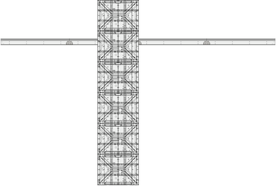
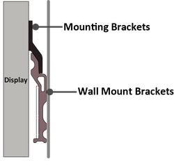
-
Ensure the Mounting Brackets sit securely on the Wall Mount Brackets as shown below.
- Repeat Step 1~2 for the second Cabinet.
- Install the first and second Cabinets together with the provided screws (M8 x 20 mm).
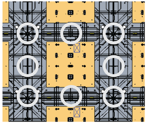
-
Check for unevenness of the Cabinets by rubbing the cross section between each Cabinet. If the cross section is not aligned, loosen the M8 screws slightly and tap the Cabinets until the cross section is flat.
-
Repeat Step 1~7 for the remaining Cabinets, ensuring that the Mounting Brackets sit securely on the Wall Mount Brackets, and that the Cabinets are properly secured together.
Note: Refer to the included Appendix B to identify the Cabinets and installation sequence. - After installing all Cabinets, cut the rubber hole plugs to size along the cross with a knife (see the included Appendix B for the position of the hole plugs).


Connecting and Installing the System Control Box
The left and right sides of the System Control Box are pre-installed with its Covers in the factory. The main system control board is on the right.
The safety wires are used to prevent the Right Cover from falling when accessing the System Control Box. Please ensure that the safety wires are never removed.
Use caution as the System Control Box panel is separated into two pieces with wires attached (See the included Appendix B for example system wiring diagrams).

-
Carefully place the System Control Box on stable furniture that can safely support the System Control Box.
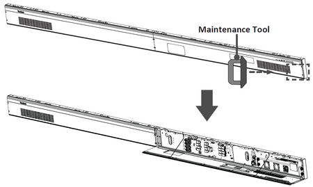
-
To open the Right Cover, slowly bring the supplied System Control Box Maintenance Tool near the surface of the Right Cover where the steel plate is located. Then, the Right Cover should detach from the System Control Box magnetically.
DO NOT try to remove or disconnect the safety wires. Please ensure that the safety wires are never removed.
-
Remove the Left Cover by gripping the top edge of the Cover and pulling it toward you. The Left Cover should simply lift away.
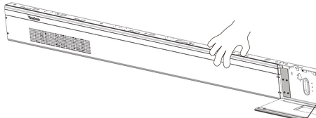
-
Secure the System Control Box panel with the Connector Plate using the provided screws (M3 x 6 mm).
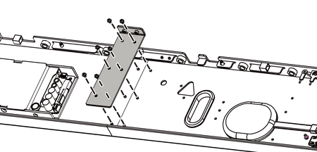
-
Further secure the Connector Plate with the two provided screws (M3 x 5 mm).
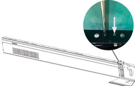
-
Install the System Control Box to the bottom of the Cabinets with the provided screws (M8 x 20 mm).
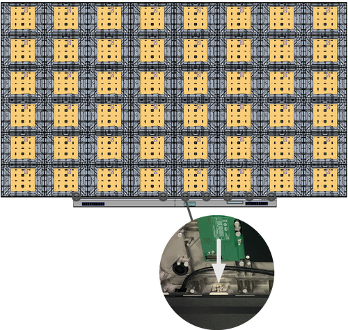
-
Connect the Power and Network Cables from the System Control Box to each Cabinet. Start from the bottom and move to the top (see the included Appendix B for example system wiring diagrams, including wire colors and connection points).
Note: Ensure to match the corresponding letters on the Cables to the Cabinets (A to A, B to B, C to C, D to D, and so on). -
Connect the LED Display's left speaker to the Audio Out port.
Note: Ensure that the right speaker is properly connected to the other Audio Out port. - Connect the AC unit(s) of the System Control Box to the main system control board.
-
Ensure the AC unit(s) of the System Control Box is properly connected.
DO NOT connect the System Control Box Power Cable(s) at this time.
- The neutral wires (usually white/blue) are connected to the "N1", "N2", and "N" terminals.
- The hot wires (usually black/brown) are connected to the "L1", "L2", and "L" terminals.
- The input and output terminals are properly grounded (usually in green).
The meaning of wiring color may vary by country.
-
After connecting all Cables and wires, hold the top edge of the Right Cover toward the System Control Box to replace it. Once the Right Cover is replaced, it will be held in place magnetically.
Note: Ensure the Power Button cable is connected before securing the Right Cover.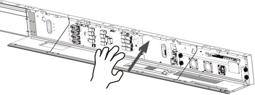
-
Replace the Left Cover by aligning it properly with the System Control Box; then the Left Cover should attach magnetically.


Installing the LED Modules
Please wear Anti-Static Gloves before handling the LED Modules.
To avoid direct contact with the LED Modules, please remove watches, rings, bracelets, or other metal objects.
Use caution when installing the LED Modules.
-
Starting from the LED Module labeled "1" in the top left corner, align each LED Module with the Cabinet, then carefully press the Module into place.
Note: The arrow marks on the back of the LED Modules should be pointing up.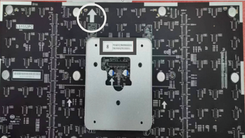
-
Attach the remaining LED Modules onto the Cabinets. Install from top left and move to bottom right, ensuring to match the corresponding numbers on the Module to the Cabinet. See the included Appendix C for further guidance on the LED Modules.
Note: Before installing the LED Module, ensure that each Module is flush and that there is little to no gap between each. It may be necessary to gently tap the module to make it flush.

Installing the Screen Bezels
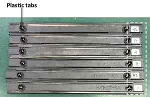
The Screen Bezels' plastic tabs are pre-installed onto the Bezels. Ensure all plastic tabs are properly mounted before installing the Screen Bezels onto the screen.
The Screen Bezels' plastic tabs are pre-installed onto the Bezels. Ensure all plastic tabs are properly mounted before installing the Screen Bezels onto the screen.
The label indicates the top of each Screen Bezel. To ensure the Bezels are installed in the correct position, please use the labels on the inside of the Bezels as a guide.

-
Place the Screen Bezel to the correct side of the screen to attach. Start from the left and move to the right (See the included Appendix C for the location where each Screen Bezel should be installed).
Note:- Ensure the label side of the Screen Bezel is facing the screen.
- Before installing the Screen Bezels, check the label of each Bezel as the label helps you know which side ("L" = left side & "R" = right side) to attach.
- If a Screen Bezel does not seem to fit, lift it up with caution and check if it is on the correct side to install. If the Bezel does not seem to fit at all, please contact your reseller. DO NOT force it into place.
-
Align the plastic tabs of the Screen Bezel with the holes provided in the screen.

-
Press down on the Screen Bezel until you hear it click into place.
- Place the remaining Screen Bezels onto the left and right sides of the screen.

Turning On the LED Display
-
Make sure the System Control Box Power Cable(s) is connected and plugged into power outlets.
Note: When the System Control Box Power Cable(s) is connected to power outlet(s), the Power Indicator Light will be a steady red. This means the LED Display is in standby mode. -
Your LED Display is now ready to power on.
Hidden Installation
You can find all appendixes at the end of the Installation Guide in the package.
Wall Mounting
Before the installation, please ensure the supplied Wall Mount Brackets match the ones illustrated in the included Appendix A.
-
Please take a moment to check the following when deciding the installation location. However, for the best results, it is recommended to ask your reseller or licensed professional to install the LED Display.
- The wall space.
- The wall type.
- The power consumption.
- The installation type.
- Cable pathways between the Cabinets, and between the Cabinets and System Control Box.
Note: Refer to the included Appendix A for the detailed instructions on mounting the Wall Mount Brackets, including minimum space requirements. -
Install the first Upper Wall Mount Bracket with the provided screws (M8 x 80 mm Expansion).
-
Repeat Step 2, ensuring the second Upper Wall Mount Bracket is level with the first Upper Bracket.
Note: It is recommended to use a laser or torpedo level. - Repeat Step 2~3 for the remaining Upper Wall Mount Bracket(s).
-
Install the Lower Wall Mount Brackets in the same manner as the Upper Wall Mount Brackets.
Note: You can also install the Upper Wall Mount Brackets, hang the screen, and then install the Lower Wall Mount Brackets for a more precise fit.
Installing the Cabinets
Before installing the Cabinets on the Wall Mount Brackets, it is recommended to refer to the wiring diagram provided in the included Appendix B first to decide how you want to route the Cables for the power and network connections to the Cabinets.
Additionally, the rubber hole plugs installed on the Cabinets are used to protect the Power and Network Cables from rubbing against any pointed edges. After installing all Cabinets, use a knife to cut the rubber hole plugs to size along the cross according to the thickness of the Cables.
- Locate the Cabinet to install the left Upper System Control Box Mount Bracket (see the included Appendix B to identify the Cabinet).
Note:
- One Cabinet is divided into separate sections. You can identify these Cabinet sections by the labels on each section or the package.
- The arrow marks on each Cabinet section should be pointing up.
- Place each section of the Cabinet on stable furniture that can safely support them.
- Attach the Cabinet sections together with the provided screws (M8 x 20 mm).
- Install the left Upper System Control Box Mount Bracket to the side of the two assembled Cabinet with the provided screws (M8 x 20 mm).
- Repeat Step 1~4 for the right Upper System Control Box Mount Bracket.
- Repeat Step 2~3 for the first Cabinet. Start from the center, and move to the right and left sides of the Wall Mount Brackets (see the included Appendix B to identify Cabinet sections and installation sequence)
- Carefully lift the assembled Cabinet onto the center of the Upper Wall Mount Brackets.
-
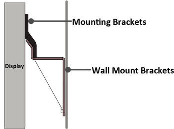
Ensure the Mounting Brackets sit securely on the Wall Mount Brackets as shown below.
- Repeat Step 2~3 for the second Cabinet, ensuring it sit securely on the Wall Mount Brackets.
- Install the first and second Cabinets together with the provided screws (M8 x 20 mm).
-
Check for unevenness of the Cabinets by rubbing the cross section between each Cabinet. If the cross section is not aligned, loosen the M8 screws slightly and tap the Cabinets until the cross section is flat.
-
Assemble and install the remaining Cabinets in the same manner as the first two Cabinets. Ensure the Mounting Brackets sit securely on the Wall Mount Brackets, and that the Cabinets are properly secured together.
Note: Refer to the included Appendix B to identify the Cabinets and installation sequence. - After installing all Cabinets, cut the rubber hole plugs to size along the cross with a knife (see the included Appendix B for the position of the hole plugs).

Connecting and Installing the System Control Box
The left and right sides of the System Control Box are pre-installed with its Covers in the factory. The main system control board is on the right.
The safety wires are used to prevent the Right Cover from falling when accessing the System Control Box. Please ensure that the safety wires are never removed.
Use caution as the System Control Box panel is separated into two pieces with wires attached.
Before installing the System Control Box, the Power and Network Cables of the Cabinets at the lowest row must be routed through the holes provided in the System Control Box from behind (see the included Appendix B for example system wiring diagram).
- Carefully place the System Control Box on stable furniture that can safely support the System Control Box.
- The rubber hole plugs installed on the rear of the System Control Box are used to protect the Cables from rubbing against any pointed edges. Use a knife to cut the hole to size along the cross.
-
To open the Right Cover, slowly bring the supplied System Control Box Maintenance Tool near the surface of the Right Cover where the steel plate is located. Then, the Right Cover should detach from the System Control Box magnetically.
DO NOT try to remove or disconnect the safety wires. Please ensure that the safety wires are never removed.
-
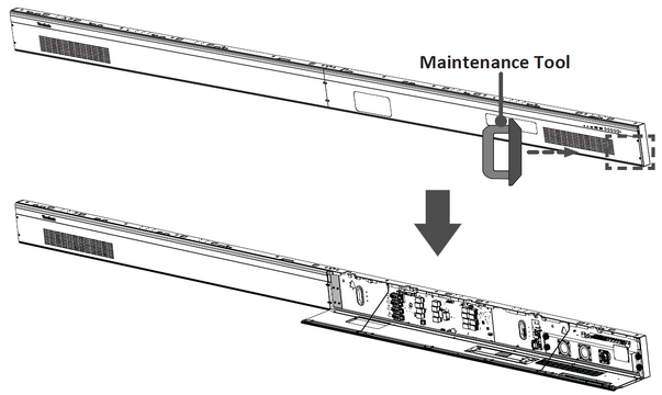 The LD-SCB-011/LD-SCB-021 control box
 -
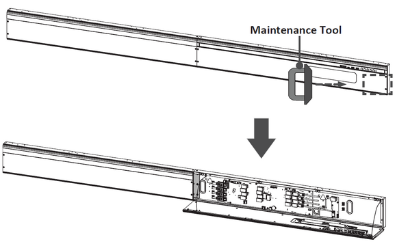 TThe LD-SCB-012/LD-SCB-022 control box
-
Remove the Left Cover by gripping the top edge of the Cover and pulling it toward you. The Left Cover should simply lift away.
-
Secure the System Control Box panel with the Connector Plate using the provided screws (M3 x 6 mm).
-
Further secure the Connector Plate with the two provided screws (M3 x 5 mm).
-
Install the short side of the Lower System Control Box Mount Bracket onto the top of the System Control Box with the provided screws (M3 x 6 mm).
Note:- There are two Lower System Control Box Mount Brackets to install.
- The following illustrations about the installation locations of the Lower System Control Box Mount Brackets are for reference only. See the included Appendix A for the actual installation locations of the Lower Mount Brackets.
-
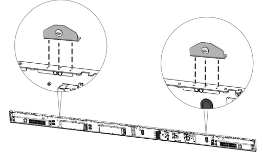 The LD-SCB-011/LD-SCB-021 control box
 -
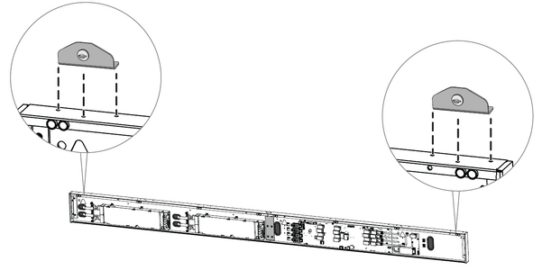 The LD-SCB-012/LD-SCB-022 control box
-
Install the provided screw (M8 x 16 mm) on the Lower System Control Box Mount Bracket. Thread the provided M8 nut onto the screw and fully tighten the nut.
-
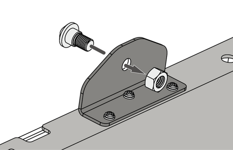 Installing the provided screw and nut to the Brackets (Rear View)
-
-
Repeat Step 7 for the other Lower System Control Box Mount Bracket.
-
Remove the pre-installed Power and Network Cables of the Cabinets from the System Control Box.
Note: It is recommended to take photos of the completed wiring in the left and main system control boards before removing the Cables. -
After removing the pre-installed Power and Network Cables of the Cabinets, connect one end of the longer Network Cable to the network port that was disconnected from the System Control Box in Step 10.
Note:- Refer to the included Appendix B for example system wiring diagrams, including wire colors and connection points.
- Ensure to match the corresponding letters on the Cables to the network ports of the System Control Box (A to A, B to B, C to C, and so on).
-
Carefully thread the Network Cables through the hole provided in the System Control Box to the rear (see the included Appendix B for the position of the cable holes). Avoid sharp bends in the Cables.
Note: The rubber hole plugs must always be placed in the holes. -
After threading all Network Cables of the Cabinets, connect the longer Power Cables to the AC unit(s) of the System Control Box.
DO NOT connect the System Control Box Power Cable(s) at this time.
- Connect the neutral wires (usually white/blue) to the "N1", "N2", and "N" terminals.
- Connect the hot wires (usually black/brown) to the "L1", "L2", and "L" terminals.
- Connect the ground wires (usually in green) to the ground terminals.
The meaning of wiring color may vary by country.
Use the provided wrench to tighten the neutral, hot, and ground conductors in the terminals properly.
-
Thread the Power Cables of the Cabinets through the hole provided in the System Control Box to the rear (see the included Appendix C for the position of the cable holes). Avoid sharp bends in the Cables.
Note:- The rubber hole plugs must always be placed in the holes.
- Before threading the Cables through, ensure that the output and input terminals are properly grounded, and that the wire colors/labels are matched with the marked terminals and each wire is screwed firmly to its corresponding terminal.
-
Connect the AC unit(s) of the System Control Box to the main system control board.
-
Connect the LED Display's left speaker to the Audio Out port.
Note: Ensure that the right speaker is properly connected to the other Audio Out port. - Connect the IR Extension Cable to the main system control board. Then, route it through the hole of the System Control Box to the rear.
Note: Refer to the included Appendix C for the position of the cable holes.
-
After connecting all Cables and wires, hold the top edge of the Right Cover toward the System Control Box to replace it. Once the Right Cover is replaced, it will be held in place magnetically.
Note: Ensure the Power Button cable is connected before securing the Right Cover. -
Replace the Left Cover by aligning it properly with the System Control Box; then the Left Cover should attach magnetically.
-
Align the Lower System Control Box Mount Brackets with the Upper Mount Brackets to attach.
- Thread the Power and Network Cables through the holes provided in the Cabinets to the front.
Note: Ensure to match the corresponding letters on the Cables to the Cabinets (A to A, B to B, C to C, and so on).
- Carefully place the Lower System Control Box Mount Brackets onto the Upper System Control Box Mount Brackets.
-
Ensure the Lower System Control Box Mount Brackets sit securely on the Upper.
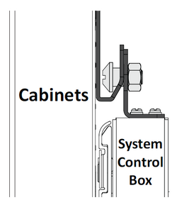
- After installing the System Control Box, connect the Power and Network Cables from the System Control Box to each Cabinet. Start from the bottom and move to the top (see the included Appendix B for example system wiring diagrams, including wire colors and connection points).


Installing the LED Modules
Please wear Anti-Static Gloves before handling the LED Modules.
To avoid direct contact with the LED Modules, please remove watches, rings, bracelets, or other metal objects.
Use caution when installing the LED Modules.
-
Starting from the LED Module labeled "1" in the top left corner, align each LED Module with the Cabinet, then carefully press the Module into place.
Note: The arrow marks on the back of the LED Modules should be pointing up. -
Attach the remaining LED Modules onto the Cabinets. Install from top left and move to bottom right, ensuring to match the corresponding numbers on the Module to the Cabinet. See the included Appendix C for further guidance on the LED Modules.
Note: Before installing the LED Module, ensure that each Module is flush and that there is little to no gap between each. It may be necessary to gently tap the module to make it flush.
Installing the Screen Bezels
The Screen Bezels' plastic tabs are pre-installed onto the Bezels. Ensure all plastic tabs are properly mounted before installing the Screen Bezels onto the screen.
The Screen Bezels' plastic tabs are pre-installed onto the Bezels. Ensure all plastic tabs are properly mounted before installing the Screen Bezels onto the screen.
The label indicates the top of each Screen Bezel. To ensure the Bezels are installed in the correct position, please use the labels on the inside of the Bezels as a guide.
-
Place the Screen Bezel to the correct side of the screen to attach. Start from the left and move to the right (See the included Appendix C for the location where each Screen Bezel should be installed).
Note:- Ensure the label side of the Screen Bezel is facing the screen.
- Before installing the Screen Bezels, check the label of each Bezel as the label helps you know which side ("L" = left side & "R" = right side) to attach.
- If a Screen Bezel does not seem to fit, lift it up with caution and check if it is on the correct side to install. If the Bezel does not seem to fit at all, please contact your reseller. DO NOT force it into place.
-
Align the plastic tabs of the Screen Bezel with the holes provided in the screen.
-
Press down on the Screen Bezel until you hear it click into place.
- Place the remaining Screen Bezels onto the left and right sides of the screen.
Turning On the LED Display
-
Make sure the System Control Box Power Cable(s) is connected and plugged into power outlet(s).
Note: When the System Control Box Power Cable(s) is connected to power outlet(s), the Power Indicator Light will be a steady red. This means the LED Display is in standby mode. -
Your LED Display is now ready to power on.
Separate Installation
You can find all appendixes at the end of the Installation Guide in the package.
Wall Mounting
Before the installation, please ensure the supplied Wall Mount Brackets match the ones illustrated in the included Appendix A.
-
Please take a moment to check the following when deciding the installation location. However, for the best results, it is recommended to ask your reseller or licensed professional to install the LED Display.
- The wall space.
- The wall type.
- The power consumption.
- The installation type.
- Cable pathways between the Cabinets, and between the Cabinets and System Control Box.
Note: Refer to the included Appendix A for the detailed instructions on mounting the Wall Mount Brackets, including minimum space requirements. - Install the first Upper Wall Mount Bracket with the provided screws (M8 x 80 mm Expansion).
- Repeat Step 2, ensuring the second Upper Wall Mount Bracket is level with the first Upper Bracket.
Note: It is recommended to use a laser or torpedo level.
-
After mounting the first and second Upper Wall Mount Brackets to the wall, secure them with the Wall Mount Connector Plate using the six provided screws (PM6 x 10 mm).
- Repeat Step 2~4 for the remaining Upper Wall Mount Bracket(s).
- Install the Lower Wall Mount Brackets in the same manner as the Upper Wall Mount Brackets.
Note: You can also install the Upper Wall Mount Brackets, hang the screen, and then install the Lower Wall Mount Brackets for a more precise fit.
- After installing the Upper and Lower Wall Mount Brackets, please mark and pre-drill the mounting and cable access holes for the System Control Box (see Appendix B for the position of the required holes).
Installing the Cabinets
Before installing the Cabinets on the Wall Mount Brackets, it is recommended to refer to the wiring diagram provided in the included Appendix B first to decide how you want to route the Cables for the power and network connections to the Cabinets.
Additionally, the rubber hole plugs installed on the Cabinets are used to protect the Power and Network Cables from rubbing against any pointed edges. After installing all Cabinets, use a knife to cut the rubber hole plugs to size along the cross according to the thickness of the Cables.
- Place each section of the Cabinet on stable furniture that can safely support them. Start with the Cabinets from the center, then move to the right and left sides of the Wall Mount Brackets (see the included Appendix B to identify Cabinet sections and installation sequence).
Note:
- One Cabinet is divided into separate sections. You can identify these Cabinet sections by the labels on each section or the package.
- The arrow marks on each Cabinet section should be pointing up.
- Attach the Cabinet sections together with the provided screws (M8 x 20 mm).
-
Carefully lift the assembled Cabinet onto the center of the Upper Wall Mount Brackets.
Note: The illustration below is provided for reference only and may differ from the actual product appearance. -
Ensure the Mounting Brackets sit securely on the Wall Mount Brackets as shown below.
- Repeat Step 1~2 for the second Cabinet.
- Install the first and second Cabinets together with the provided screws (M8 x 20 mm).
-
Check for unevenness of the Cabinets by rubbing the cross section between each Cabinet. If the cross section is not aligned, loosen the M8 screws slightly and tap the Cabinets until the cross section is flat.
-
Repeat Step 1~7 for the remaining Cabinets, ensuring that the Mounting Brackets sit securely on the Wall Mount Brackets, and that the Cabinets are properly secured together.
Note: Refer to the included Appendix B to identify the Cabinets and installation sequence. - After installing all Cabinets, cut the rubber hole plugs to size along the cross with a knife (see the included Appendix B for the position of the hole plugs).
Connecting and Installing the System Control Box
The left and right sides of the System Control Box are pre-installed with its Covers in the factory. The main system control board is on the right.
The safety wires are used to prevent the Right Cover from falling when accessing the System Control Box. Please ensure that the safety wires are never removed.
Use caution as the System Control Box panel is separated into two pieces with wires attached.
Before installing the System Control Box, the Power and Network Cables of the Cabinets at the lowest row must be routed through the holes provided in the System Control Box from behind (see the included Appendix B for example system wiring diagram).
-
At the lowest row of the Cabinets, connect the connector of the longer Power Cable to the power connector of the Cabinet. Then, connect one end of the longer Network Cable to the network port of the Cabinet.
Note:
- The longer Power and Network Cables are supplied in the case.
- Ensure to match the corresponding letters on the Cables to the Cabinets (A to A, B to B, C to C, and so on).
- After connecting all the Power and Network Cables, carefully thread them through the holes provided in the Cabinets and run the Cables behind the Cabinets from the top cable access hole through the bottom cable access holes.
Avoid sharp bends in the Cables.
The rubber hole plugs must always be placed in the holes.
- Carefully place the System Control Box on stable furniture that can safely support the System Control Box.
- The rubber hole plugs installed on both the System Control Box and Cabinets are used to protect the Cables from rubbing against any pointed edges. Use a knife to cut the hole to size along the cross.
-
To open the Right Cover, slowly bring the supplied System Control Box Maintenance Tool near the surface of the Right Cover where the steel plate is located. Then, the Right Cover should detach from the System Control Box magnetically.
DO NOT try to remove or disconnect the safety wires. Please ensure that the safety wires are never removed.
-
The LD-SCB-011/LD-SCB-021 control box
-
TThe LD-SCB-012/LD-SCB-022 control box
-
Remove the Left Cover by gripping the top edge of the Cover and pulling it toward you. The Left Cover should simply lift away.
-
Secure the System Control Box panel with the Connector Plate using the provided screws (M3 x 6 mm).
-
Further secure the Connector Plate with the two provided screws (M3 x 5 mm).
-
Place the System Control Box accordingly over the drilled mounting holes to attach.
- Carefully thread the Power and Network Cables through the holes provided in the System Control Box from behind. Ensure to use the correct cable holes for the Power and Network Cables.
Note:
- The rubber hole plugs must always be placed in the holes.
- Refer to the included Appendix B for the position of the cable holes.
- After threading the Power and Network Cables, install the System Control Box onto the wall with the provided screws and lock washers (M8 x 80 mm Expansion).
-
Remove the pre-installed Power and Network Cables of the Cabinets from the System Control Box.
Note: It is recommended to take photos of the completed wiring in the left and main system control boards before removing the Cables. - After removing the pre-installed Power and Network Cables of the Cabinets, connect the other end of the longer Network Cable to the network port that was disconnected from the System Control Box in Step 12.
-
After connecting all Network Cables of the Cabinets, connect the longer Power Cables to the AC unit(s) of the System Control Box.
DO NOT connect the System Control Box Power Cable(s) at this time.
- Connect the neutral wires (usually white/blue) to the "N1", "N2", and "N" terminals.
- Connect the hot wires (usually black/brown) to the "L1", "L2", and "L" terminals.
- Connect the ground wires (usually in green) to the ground terminals.
The meaning of wiring color may vary by country.
Use the provided wrench to tighten the neutral, hot, and ground conductors in the terminals properly.
- Connect the AC unit(s) of the System Control Box to the main system control board.
- Connect the LED Display's left speaker to the Audio Out port.
Note: Ensure that the right speaker is properly connected to the other Audio Out port.
- Connect the IR Extension Cable to the main system control board. Then, route it through the hole of the System Control Box to the rear.
Note: Refer to the included Appendix B for the position of the cable holes.
-
After connecting all Cables and wires, hold the top edge of the Right Cover toward the System Control Box to replace it. Once the Right Cover is replaced, it will be held in place magnetically.
Note: Ensure the Power Button cable is connected before securing the Right Cover. -
Replace the Left Cover by aligning it properly with the System Control Box; then the Left Cover should attach magnetically.
- After replacing the System Control Box Covers, connect the Power and Network Cables between the Cabinets (see the included Appendix B for the wiring instructions).
- Install System Control Box Trim Strip(s) on the top of the System Control Box.
Installing the LED Modules
Please wear Anti-Static Gloves before handling the LED Modules.
To avoid direct contact with the LED Modules, please remove watches, rings, bracelets, or other metal objects.
Use caution when installing the LED Modules.
-
Starting from the LED Module labeled "1" in the top left corner, align each LED Module with the Cabinet, then carefully press the Module into place.
Note: The arrow marks on the back of the LED Modules should be pointing up. -
Attach the remaining LED Modules onto the Cabinets. Install from top left and move to bottom right, ensuring to match the corresponding numbers on the Module to the Cabinet. See the included Appendix C for further guidance on the LED Modules.
Note: Before installing the LED Module, ensure that each Module is flush and that there is little to no gap between each. It may be necessary to gently tap the module to make it flush.
Installing the Screen Bezels
The Screen Bezels' plastic tabs are pre-installed onto the Bezels. Ensure all plastic tabs are properly mounted before installing the Screen Bezels onto the screen.
The Screen Bezels' plastic tabs are pre-installed onto the Bezels. Ensure all plastic tabs are properly mounted before installing the Screen Bezels onto the screen.
The label indicates the top of each Screen Bezel. To ensure the Bezels are installed in the correct position, please use the labels on the inside of the Bezels as a guide.
-
Place the Screen Bezel to the correct side of the screen to attach. Start from the left and move to the right (See the included Appendix C for the location where each Screen Bezel should be installed).
Note:- Ensure the label side of the Screen Bezel is facing the screen.
- Before installing the Screen Bezels, check the label of each Bezel as the label helps you know which side ("L" = left side & "R" = right side) to attach.
- If a Screen Bezel does not seem to fit, lift it up with caution and check if it is on the correct side to install. If the Bezel does not seem to fit at all, please contact your reseller. DO NOT force it into place.
-
Align the plastic tabs of the Screen Bezel with the holes provided in the screen.
-
Press down on the Screen Bezel until you hear it click into place.
- Place the remaining Screen Bezels onto the left and right sides of the screen.
Turning On the LED Display
-
Make sure the System Control Box Power Cable(s) is connected and plugged into power outlet(s).
Note: When the System Control Box Power Cable(s) is connected to power outlet(s), the Power Indicator Light will be a steady red. This means the LED Display is in standby mode. -
Your LED Display is now ready to power on.