LDC031 Introduction
Product Overview
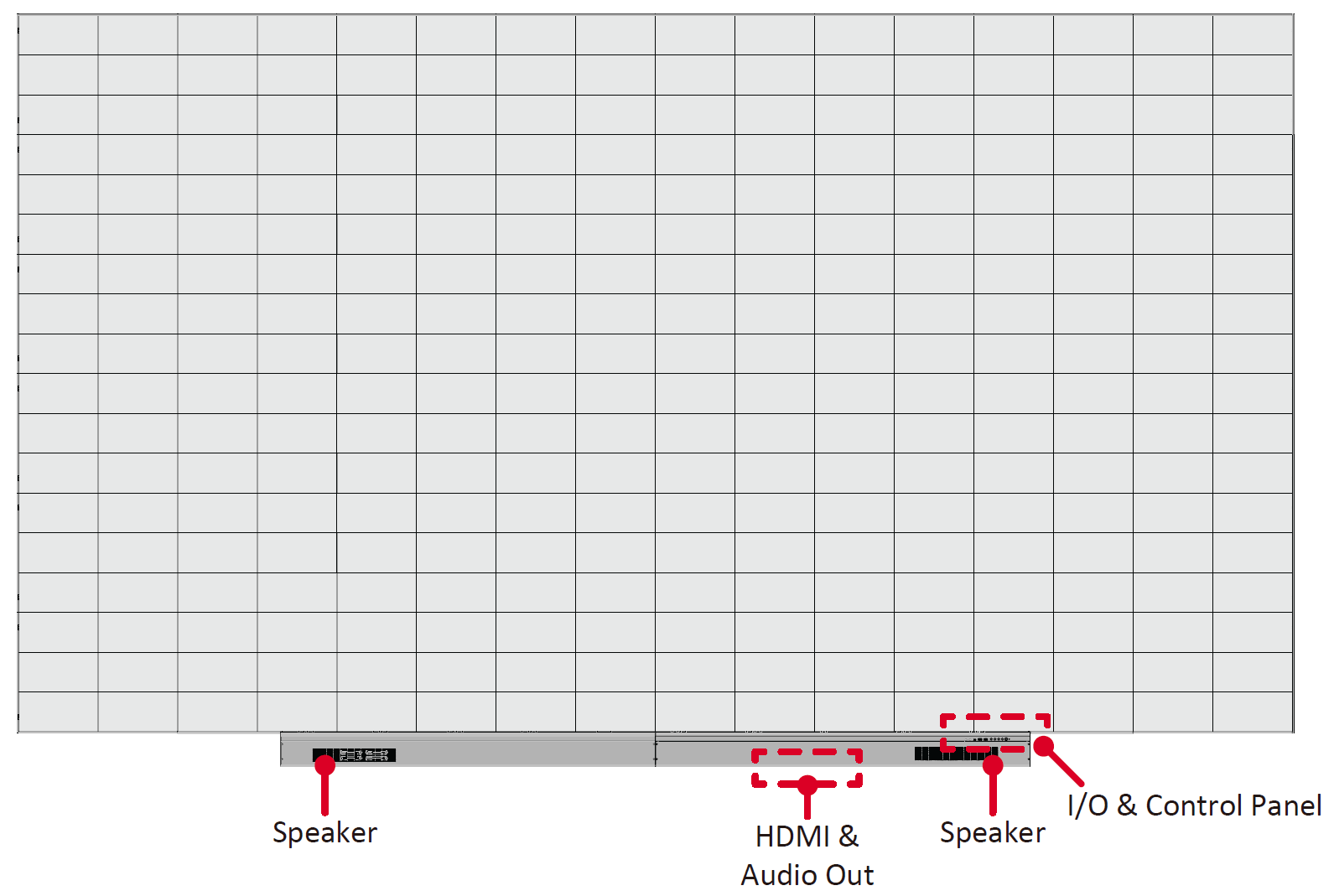
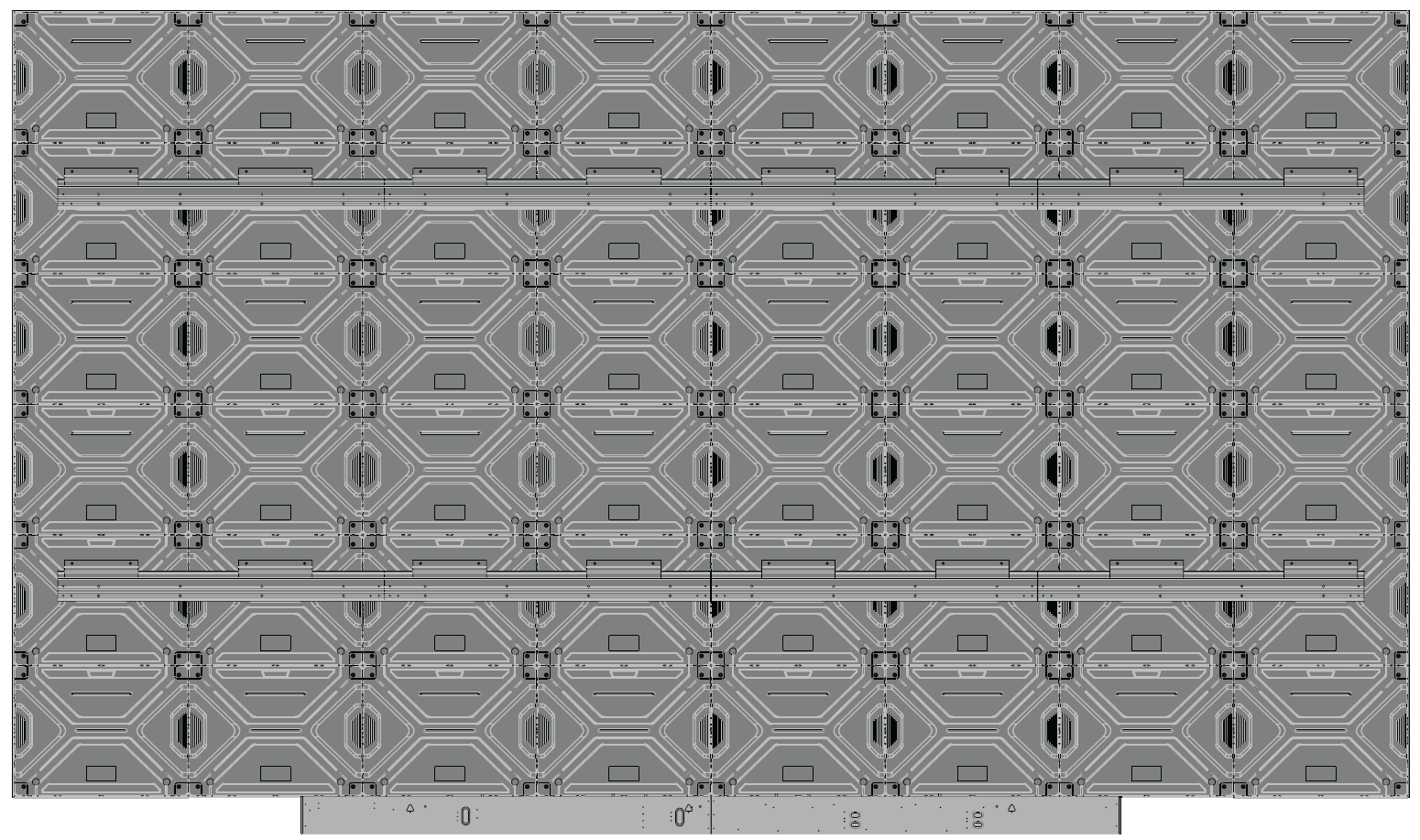
Below is an 8 x 6 cabinet example. Sizing will vary by model.
Front View
Rear View
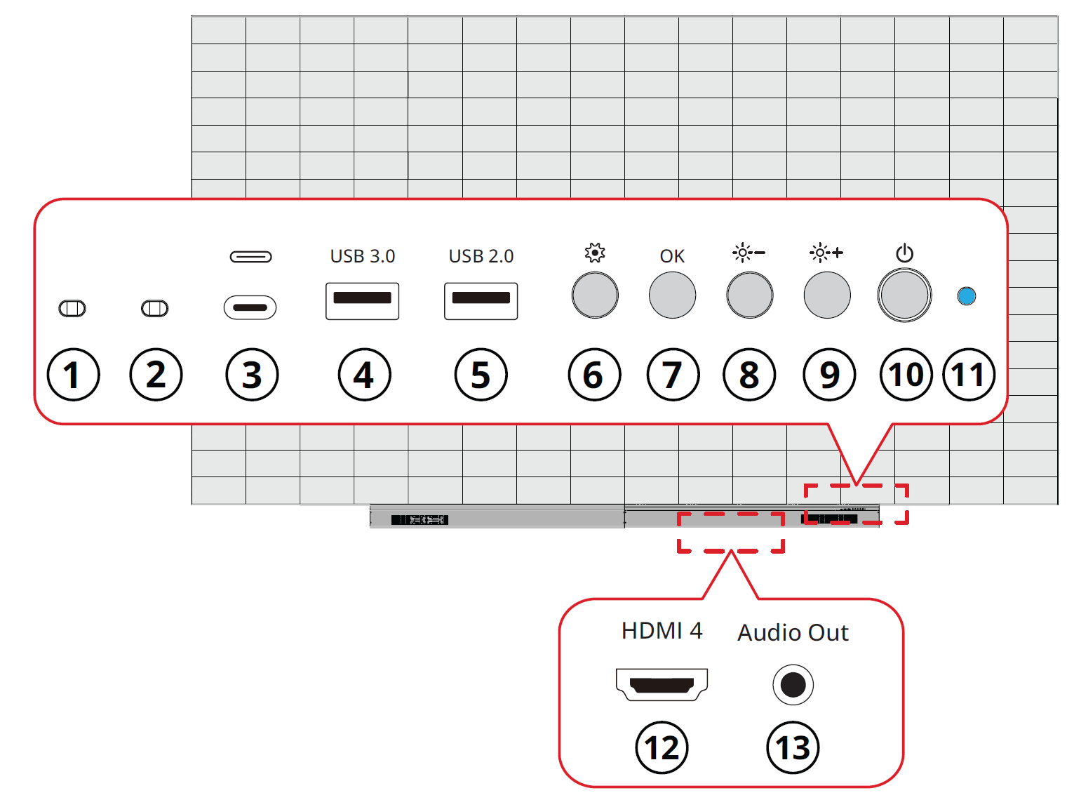
Control Panel and I/O
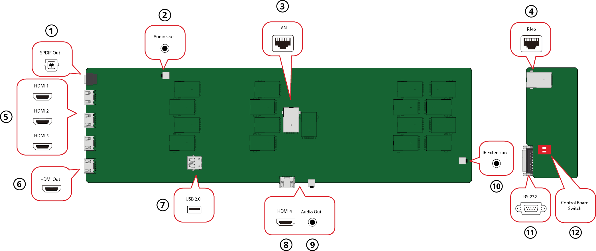
The I/O ports can be accessed by removing the right side of the System Control Box Cover.
Control Panel
| Item | Description | |
|---|---|---|
| 1 | Light Sensor | Ambient light sensor. |
| 2 | IR Receiver | Receiver for remote control signal. |
| 3 | USB Type C | USB 2.0 support (5V/1.0A). |
| 4 | USB 3.0 | USB Reader (5V/0.9A). |
| 5 | USB 2.0 | USB Reader (5V/0.5A). |
| 6 | Menu | Open the display settings or On-Screen Display (OSD) Menu. |
| 7 | Brightness/OK |
|
| 8 | Brightness Decrease | Decrease the brightness level. |
| 9 | Brightness Increase | Increase the brightness level. |
| 10 | Power | Power on, standby and wake button. |
| 11 | Indicator Light | Power status indicator light. |
| 12 | HDMI 4 | 4 High definition input: PIP/PBP, connect to PC with HDMI output, set-top box, or other video device. |
| 13 | Audio Out | Audio output to an external audio device. |
I/O Ports
| Item | Description | |
|---|---|---|
| 1 | S/PDIF Out | Multi-channel optical audio signal. |
| 2 | Audio OUT | Audio output to an external speaker. |
| 3 | LAN | Standard RJ45 (10M/100M/1000M) Internet connection interface. |
| 4 | RJ45 | Standard RJ45 control connection interface. |
| 5 | HDMI 1/2/3 | High definition input: PIP/PBP ,connect to PC with HDMI output, set-top box, or other video device. |
| 6 | HDMI Out | Extend the display's content out to another display device. |
| 7 | USB 2.0 | USB Type A port for power (5V/2A). |
| 8 | HDMI 4[1] | High definition input: PIP/PBP ,connect to PC with HDMI output, set-top box, or other video device. |
| 9 | Audio Out[1] | Audio output to an external audio device. |
| 10 | IR Extension | Connection point for an extended IR receiver. |
| 11 | RS-232 | Serial control port. |
| 12 | Control Board Switch[2] | Control switch for the control board. |


