Press and hold the Menu and Return buttons for approximately three seconds until the indicator on the remote control flashes blue.
If the pairing is successful, a pop-up message will appear on the screen.
Note: If the pairing is unsuccessful after one minute, please try again by repeating Step 1 above.
Remote Control Receiver Range
The operating range of the remote control is shown here. It has an effective range of 6 meters (20 feet), 30° degrees left and right. Please make sure there is nothing obstructing the remote control’s signal to the receiver.
IR Extension
Note: The IR Extension port is accessed by removing the System Control Box Cover
If an additional IR Receiver is needed, an IR extension cable can be connected to the IR Extension port of the display.
Inserting Remote Control Batteries
The remote control is powered by two 1.5v "AAA" batteries.
To insert batteries into the remote control:
Remove the cover on the rear of the remote control.
Insert two “AAA” batteries, ensuring the (+) symbol on the battery matches the (+) on the battery post.
Replace the cover by aligning it with the slot on the remote control and snapping the latch shut.
WARNING: There is a risk of explosion if batteries are installed with incorrect polarity.
Note:
It is recommended that you do not mix battery types.
Avoid exposure to heat or steam.
Do not allow water or other liquids to splash on the remote control. If the remote control becomes wet, wipe it dry immediately.
Always dispose of old batteries in an environmentally friendly way. Contact your local government for more information on how to dispose of batteries safely.
Wall Installation
Introduction
The step-by-step instructions in this guide are a general reference for installing the LED Display. If any details in this document are unclear, please contact your reseller for more information.
Note: It is recommended to ask your reseller or licensed professional to install the LED Display.
About the LED Display
The LED Display can be installed on the Wall or on a Trolley.
↑Hidden and Separate Installations are not applicable to the trolley.
Before Installing
Ensure there is no direct airflow from air conditioning or heating vents blowing on the display.
Avoid installing the LED Display in places with high humidity.
Due to high power usage, always use power cords specifically designed for this product.
Wood may split if holes are not pre-drilled before installing the Wall Mount Brackets.
Ensure that the wall can safely support 227 kg and the power outlet supplies enough voltage (max: 2624W; normal: 918W).
Ensure the deviation of the wall surface is < 5 mm.
Wear protective gear, such as gloves and protective shoes, when handling the LED Display.
Standard Installation
Wall Mounting
Four Wall Mount Brackets (1799 mm) are used for mounting the screen to the wall.
Ensure the wall area is an appropriate installation site.
Note:
You can also install the Upper Wall Mount Brackets, hang the screen, and then install the Lower Wall Mount Brackets for a more precise fit.
Adjustment in floor clearance and ceiling height should be made according to the actual installation site.
Using the illustration as shown below as a guide, mark at least 12 mounting holes and pre-drill them.
Install the first Upper Wall Mount Bracket with the provided screws (M8 x 80 mm Expansion for masonry; wood screws for load bearing wood).
Repeat Step 3, ensuring the second Upper Wall Mount Bracket is level with the first Upper Bracket.
Note: It is recommended to use a laser or torpedo level.
After mounting the first and second Upper Wall Mount Brackets to the wall, secure them with the Wall Mount Connector Plate using the six provided screws (PM6 x 10 mm).
Install the Lower Wall Mount Brackets in the same manner as the Upper Wall Mount Brackets. The distance between the Upper and Lower Wall Mount Brackets is 1012.5 mm.
After installing both Upper and Lower Wall Mount Brackets, the installation wall should look like:
Installing the Cabinets
Carefully lift Cabinet "C" onto the center of the Upper Wall Mount Brackets.
Note:
One Cabinet weighs around 37.2 kg (82.01 lb).
You can identify Cabinet sections by the labels on the package.
The arrow marks on each Cabinet section should be pointing up.
Ensure the Mounting Brackets sit securely on the Wall Mount Brackets as shown below.
Lift Cabinet "D" and install it on the right side of Cabinets "C". Install the two Cabinets together with the provided screws (M8 x 20 mm).
Note: There are 12 screws between each Cabinet.
Check for unevenness of the Cabinets by rubbing the cross section between each Cabinet. If the cross section is not aligned, loosen the M8 screws slightly and tap the Cabinets until the cross section is flat.
Place the remaining Cabinets onto the Wall Mount Brackets. Install from the center to the right and left sides of the Wall Mount Brackets.
Note: The installation sequence by Cabinet: C ➜ D ➜ B ➜ E ➜ A ➜ F
Connecting the System Control Box
The left and right sides of the System Control Box are pre-installed with its Covers in the factory. The main system control board is on the right.
The safety wires are used to prevent the Right Cover from falling when accessing the System Control Box. Please ensure that the safety wires are never removed.
Use caution as the System Control Box panel is separated into two pieces with wires attached.
Carefully place the System Control Box on stable furniture that can safely support the System Control Box.
To open the Right Cover, slowly bring the supplied System Control Box Maintenance Tool near the surface of the Right Cover where the steel plate is located. Then, the Right Cover should detach from the System Control Box magnetically.
DO NOT try to remove or disconnect the safety wires. Please ensure that the safety wires are never removed.
Remove the Left Cover by gripping the top edge of the Cover and pulling it toward you. The Left Cover should simply lift away.
Secure the System Control Box panel with the Connector Plate using the provided screws (M3 x 6 mm).
Further secure the Connector Plate with the two provided screws (M3 x 5 mm).
Align the holes of the Cabinets with the System Control Box to attach.
Carefully route the Network and Power Cables through the holes in each Cabinet.
Install the System Control Box to the bottom of the Cabinets with the provided screws (M8 x 20 mm).
Note: There are nine threaded holes between the Cabinets and the System Control Box.
Connect the Power and Network Cables from the System Control Box to each Cabinet. Ensure to match the corresponding letters on the Cables to the Cabinets (A to A, B to B, C to C, and so on).
Note:
Each Cabinet has one Power and one Network Cable to connect.
Only the Cables at the lowest row of the Cabinets need to be connected.
Connect the left system control board to the main system control board.
Connect the LED Display's left speaker to the Audio Out port of the system control board.
Note: Ensure that the right speaker is properly connected to the other Audio Out port. See the Introduction section for the position of the LED Display's left and right speakers.
Ensure the AC unit of the System Control Box is properly connected.
DO NOT connect the System Control Box Power Cables at this time.
The neutral wires (usually white/blue) are connected to the "N1", "N2", and "N" terminals.
The hot wires (usually black/brown) are connected to the "L1", "L2", and "L" terminals.
The input and output terminals are properly grounded (3 x AC OUT and 2 x AC IN, usually in green).
The meaning of wiring color may vary by country.
After connecting all Cables and wires, hold the top edge of the Right Cover toward the System Control Box to replace it. Once the Right Cover is replaced, it will be held in place magnetically.
Note: Ensure the Power Button cable is connected before securing the Right Cover.
Replace the Left Cover by aligning it properly with the System Control Box; then the Left Cover should attach magnetically.
Installing the LED Modules
Please wear Anti-Static Gloves before handling the LED Modules.
To avoid direct contact with the LED Modules, please remove watches, rings, bracelets, or other metal objects.
Use caution when installing the LED Modules.
Starting from the LED Module labeled "1" in the top left corner, align each LED Module with the Cabinet, then carefully press the Module into place.
Note: The arrow marks on the back of the LED Modules should be pointing up.
Attach the remaining LED Modules onto the Cabinets. Install from top left and move to bottom right, ensuring to match the corresponding numbers on the Module to the Cabinet.
Note: Before installing the LED Module, ensure that each Module is flush and that there is little to no gap between each. It may be necessary to gently tap the module to make it flush.
Installing the Screen Bezels
The Screen Bezels' plastic tabs are pre-installed onto the Bezels. Ensure all plastic tabs are properly mounted before installing the Screen Bezels onto the screen.
The label indicates the top of each Screen Bezel. To ensure the Bezels are installed in the correct position, please use the labels on the inside of the Bezels as a guide.
Place the Screen Bezel to the correct side of the screen to attach. Start from the left and move to the right.
Note:
Ensure the label side of the Screen Bezel is facing the screen.
Before installing the Screen Bezels, check the label of each Bezel as the label helps you know which side ("L" = left side & "R" = right side) to attach.
The illustration below shows the location where each Screen Bezel should be installed.
Align the plastic tabs of the Screen Bezel with the holes provided in the screen.
Press down on the Screen Bezel until you hear it click into place.
Place the remaining Screen Bezels onto the left and right sides of the screen.
Note: There are six Screen Bezels on either left or right side of the screen to install.
Turning On the LED Display
Make sure the System Control Box Power Cables are connected and plugged into power outlets.
Note: When the System Control Box Power Cables are connected to power outlets, the Power Indicator Light will be a steady red. This means the LED Display is in standby mode. Please refer to the User Guide for more details.
Your LED Display is now ready to power on.
Hidden Installation
When the System Control Box is installed behind the Cabinets, this installation type requires a different set of Wall Mount Brackets. You also need the System Control Box Mount Brackets to attach the System Control Box to the rear of the Cabinets.
Wall Mounting
Four Wall Mount Brackets (1335 mm) are used for mounting the screen to the wall.
Ensure the wall area is an appropriate installation site.
Note:
You can also install the Upper Wall Mount Brackets, hang the screen, and then install the Lower Wall Mount Brackets for a more precise fit.
Adjustment in floor clearance and ceiling height should be made according to the actual installation site.
Using the illustration as shown above as a guide, mark at least eight mounting holes and pre-drill them.
Install the first Upper Wall Mount Bracket with the provided screws (M8 x 80 mm Expansion for masonry; wood screws for load bearing wood).
Repeat Step 3, ensuring the second Upper Wall Mount Bracket is level with the first Upper Bracket.
Note: It is suggested to use a laser or torpedo level.
Install the Lower Wall Mount Brackets in the same manner as the Upper Wall Mount Brackets. The distance between the Upper and Lower Wall Mount Brackets is 1012.5 mm.
After installing both Upper and Lower Wall Mount Brackets, the installation wall should look like:
Installing the Cabinets
Before installing the System Control Box behind the Cabinets, the Upper System Control Box Mount Bracket must be mounted to the Cabinets first.
Place Cabinet "B" and Cabinet "D" face down on stable furniture that can safely support the two Cabinets.
Note:
One Cabinet weighs around 37.2 kg.
You can identify Cabinet sections by the labels on the package.
The arrow marks on each Cabinet section should be pointing up.
Install the Upper System Control Box Mount Bracket to the side of the two assembled Cabinets "B" and "D" as shown below using the provided screws (M8 x 20 mm).
Rear View of Cabinet "D" (left) and Cabinet "B" (right)
Carefully lift Cabinet "C" onto the center of the Upper Wall Mount Brackets.
Ensure the Mounting Brackets sit securely on the Wall Mount Brackets as shown below.
Install the Cabinet "D" to the right side of the Cabinet "C" with the provided screws (M8 x 20 mm).
Note: There are 12 screws between each Cabinet.
Check for unevenness of the Cabinets by rubbing the cross section between each Cabinet. If the cross section is not aligned, loosen the M8 screws slightly and tap the Cabinets until the cross section is flat.
Install the Cabinet "B" to the left side of the Cabinet "C" with the provided screws (M8 x 20 mm).
Place the remaining Cabinets onto the Wall Mount Brackets. Install from the center to the right and left sides of the Wall Mount Brackets.
Note: The installation sequence by Cabinet: D ➜ E ➜ C ➜ F ➜ B ➜ G ➜ A ➜ H
The Power Cables of Cabinets are built in with the System Control Box
Power Cable of Cabinet sections "A", "B", and "C"
Power Cable of Cabinet sections "D", "E", and "F"
Disconnect the Power Cables of the Cabinets from the System Control Box.
It is recommended to take photos of the completed wiring in the left and main system control boards before removing the Cables.
Replace the pre-installed Cabinet Cable Extension with the longer Cabinet Cable Extension. Ensure to match the corresponding letter on the longer Cabinet Cable Extension to the Power Cable.
Note: Cabinets are labeled on both the Power Cables and Cabinet Cable Extensions.
Fully cover the joint with the supplied electrical tape, ensuring to wrap it with at least 25 mm for better protection.
Repeat Step 2~3 for the other Cabinet Cable Extensions.
Note: There are six Cabinet Cable Extensions to connect.
Connecting the System Control Box
The left and right sides of the System Control Box are pre-installed with its Covers in the factory. The main system control board is on the right.
The safety wires are used to prevent the Right Cover from falling when accessing the System Control Box. Please ensure that the safety wires are never removed.
Use caution as the System Control Box panel is separated into two pieces with wires attached.
Before installing the System Control Box, the Power Cables of the Cabinets must be extended first. You also need the longer Cables supplied in the case for this installation type. Please refer to the Extending the Power Cables section for more details.
Carefully place the System Control Box on stable furniture that can safely support the System Control Box.
To open the Right Cover, slowly bring the supplied System Control Box Maintenance Tool near the surface of the Right Cover where the steel plate is located. Then, the Right Cover should detach from the System Control Box magnetically.
DO NOT try to remove or disconnect the safety wires. Please ensure that the safety wires are never removed.
Remove the Left Cover by gripping the top edge of the Cover and pulling it toward you. The Left Cover should simply lift away.
Secure the System Control Box panel with the Connector Plate using the provided screws (M3 x 6 mm).
Further secure the Connector Plate with the two provided screws (M3 x 5 mm).
Install the short side of the Lower System Control Box Mount Bracket onto the top of the System Control Box with the provided screws (M3 x 6 mm).
Installing the Lower System Control Box Mount Brackets onto the System Control Box (Front and Top Views)
Install the provided screw (M8 x 16 mm) on the Lower System Control Box Mount Bracket. Thread the provided M8 nut onto the screw and fully tighten the nut.
Installing the provided screw and nut to the Brackets (Rear View)
Repeat Step 7 for the other Lower System Control Box Mount Bracket.
The rubber hole plugs installed on both the System Control Box and Cabinets are used to protect the Cables from rubbing against any pointed edges. Use a knife to cut the hole to size along the cross.
System Control Box (Front View)
Cabinets (Rear View)
Remove the pre-installed Power and Network Cables of the Cabinets from the System Control Box.
Note:
There are six Power and six Network Cables to remove.
It is recommended to take photos of the completed wiring in the left and main system control boards before removing the Cables.
After removing the pre-installed Power and Network Cables of the Cabinets, connect one end of the longer Network Cable to the network port that was disconnected from the System Control Box in Step 10.
Note:
There are six Network Cables to connect.
Ensure to match the corresponding letters on the Cables to the network ports of the System Control Box (A to A, B to B, C to C, and so on).
Carefully thread the six Network Cables through the hole provided in the System Control Box to the rear. Avoid sharp bends in the Cables.
Note: The rubber hole plugs must always be placed in the holes.
After threading the Network Cables, please follow the diagram below to connect the extended Power Cables to the AC unit of the System Control Box.
DO NOT connect the System Control Box Power Cables at this time.
Connect the neutral wires (usually white/blue) to the "N1", "N2", and "N" terminals.
Connect the hot wires (usually black/brown) to the "L1", "L2", and "L" terminals.
Connect the ground wires (usually in green) to the ground terminals.
The meaning of wiring color may vary by country.
Use the provided wrench to tighten the neutral, hot, and ground conductors in the terminals properly.
Thread the Power Cables of the Cabinets through the hole provided in the System Control Box to the rear. Avoid sharp bends in the Cables.
Note:
There are two Power Cables to thread.
The rubber hole plugs must always be placed in the holes.
Before threading the Cables through, ensure that the output and input terminals (2 x AC OUT and 1 x AC IN) are properly grounded, and that the wire colors/labels are matched with the marked terminals and each wire is screwed firmly to its corresponding terminal.
Connect the AC unit of the System Control Box to the main system control board.
Connect the LED Display's left speaker to the Audio Out port.
Note: Ensure that the right speaker is properly connected to the other Audio Out port. See the Introduction section for the position of the LED Display's left and right speakers.
After the IR Extension Cable is connected, route it through the hole of the System Control Box to the rear.
After connecting all Cables and wires, hold the top edge of the Right Cover toward the System Control Box to replace it. Once the Right Cover is replaced, it will be held in place magnetically.
Note: Ensure the Power Button cable is connected before securing the Right Cover.
Replace the Left Cover by aligning it properly with the System Control Box; then the Left Cover should attach magnetically.
Align the Lower System Control Box Mount Brackets with the Upper Mount Brackets to attach.
Thread the Power and Network Cables through the holes provided in the Cabinets to the front. Ensure to match the corresponding letters on the Cables to the Cabinets (A to A, B to B, C to C, and so on).
Threading the Power and Network Cables from behind (Rear View)
Carefully place the Lower System Control Box Mount Brackets onto the Upper System Control Box Mount Brackets.
Note: To avoid sharp bends in the Cables, please pull them into the Cabinets and manage the Cables there.
Placing the Lower System Control Box Mount Brackets to the Upper (Rear View)
Ensure the Lower System Control Box Mount Brackets sit securely on the Upper.
Connect the connector of the extended Power Cable to the power port of the Cabinet. Then, connect the other end of the Network Cable to the network port of the Cabinet. Ensure to match the corresponding letters on the Cables to the Cabinets (A to A, B to B, C to C, and so on).
Note: Each Cabinet has one Power and one Network Cable to connect.
Route the Power and Network Cables around the rods provided in the Cabinets and secure the Cables to the rods with the Cable Zip Tie and screw (PM3 x 10 mm). Leave a little slack for later adjustments if needed.
Installing the LED Modules
Please wear Anti-Static Gloves before handling the LED Modules.
To avoid direct contact with the LED Modules, please remove watches, rings, bracelets, or other metal objects.
Use caution when installing the LED Modules.
Starting from the LED Module labeled "1" in the top left corner, align each LED Module with the Cabinet, then carefully press the Module into place.
Note: The arrow marks on the back of the LED Modules should be pointing up.
Attach the remaining LED Modules onto the Cabinets. Install from top left and move to bottom right, ensuring to match the corresponding numbers on the Module to the Cabinet.
Note: Before installing the LED Module, ensure that each Module is flush and that there is little to no gap between each. It may be necessary to gently tap the module to make it flush.
Installing the Screen Bezels
The Screen Bezels' plastic tabs are pre-installed onto the Bezels. Ensure all plastic tabs are properly mounted before installing the Screen Bezels onto the screen.
The label indicates the top of each Screen Bezel. To ensure the Bezels are installed in the correct position, please use the labels on the inside of the Bezels as a guide.
Place the Screen Bezel to the correct side of the screen to attach. Start from the left and move to the right.
Note:
Ensure the label side of the Screen Bezel is facing the screen.
Before installing the Screen Bezels, check the label of each Bezel as the label helps you know which side ("L" = left side & "R" = right side) to attach.
The illustration below shows the location where each Screen Bezel should be installed.
Align the plastic tabs of the Screen Bezel with the holes provided in the screen.
Press down on the Screen Bezel until you hear it click into place.
Place the remaining Screen Bezel onto the left and right sides of the screen.
At the bottom of the screen, loosen the screws securing the pre-installed Screen Bezel and remove it. This provides enough room to the bottom Screen Bezels.
Note:
There are two pre-installed Screen Bezels to remove.
The pre-installed Screen Bezels come in with two different lengths. Remove the shorter ones.
Install the bottom Screen Bezel to the screen with the four provided screws (M3 x10 mm).
Note: There are six bottom Screen Bezels to install.
Turning On the LED Display
Make sure the System Control Box Power Cables are connected and plugged into power outlets.
Note: When the System Control Box Power Cables are connected to power outlets, the Power Indicator Light will be a steady red. This means the LED Display is in standby mode. Please refer to the User Guide for more details.
Your LED Display is now ready to power on.
Separate Installation
When the System Control Box is installed apart from the Cabinets, this installation type shares the same Wall Mount Brackets as the Standard Installation. However, you will need to pre-drill additional holes for the System Control Box.
Wall Mounting
Ensure the wall area is an appropriate installation site.
Note:
You can also install the Upper Wall Mount Brackets, hang the screen, and then install the Lower Wall Mount Brackets for a more precise fit.
Adjustment in floor clearance and ceiling height should be made according to the actual installation site.
Using the illustration as shown below as a guide, mark at least 12 mounting holes and pre-drill them.
Install the first Upper Wall Mount Bracket with the provided screws (M8 x 80 mm Expansion for masonry; wood screws for load bearing wood).
Repeat Step 3, ensuring the second Upper Wall Mount Bracket is level with the first Upper Bracket.
Note: It is recommended to use a laser or torpedo level.
After mounting the first and second Upper Wall Mount Brackets to the wall, secure them with the Wall Mount Connector Plate using the six provided screws (PM6 x 10 mm).
Install the Lower Wall Mount Brackets in the same manner as the Upper Wall Mount Brackets. The distance between the Upper and Lower Wall Mount Brackets is 1012.5 mm.
After installing both Upper and Lower Wall Mount Brackets, the installation wall should look like:
Use the illustration as shown below as a guide to mark the following holes and predrill them.
At least three mounting holes for the System Control Box.
Three cable access holes, one at the top and two at the bottom. The distance between the Lower Wall Mount Bracket and the top cable access hole is 94.8 mm.
Ensure there is enough space between the mounting holes and cable access holes.
Drill Hole Spacing for System Control Box
Installing the Cabinets
The installation of the Cabinets are the same process for both the wall installation (Standard and Separate Installation) and trolley.
Carefully lift Cabinet "C" onto the center of the Upper Wall Mount Brackets.
Note:
One Cabinet weighs around 37.2 kg.
You can identify Cabinet sections by the labels on the package.
The arrow marks on each Cabinet section should be pointing up.
Ensure the Mounting Brackets sit securely on the Wall Mount Brackets as shown below.
Lift Cabinet "D" and install it on the right side of Cabinets "C". Install the two Cabinets together with the provided screws (M8 x 20 mm).
Note: There are 12 screws between each Cabinet.
Check for unevenness of the Cabinets by rubbing the cross section between each Cabinet. If the cross section is not aligned, loosen the M8 screws slightly and tap the Cabinets until the cross section is flat.
Place the remaining Cabinets onto the Wall Mount Brackets. Install from the center to the right and left sides of the Wall Mount Brackets.
Note: The installation sequence by Cabinet: C ➜ D ➜ B ➜ E ➜ A ➜ F
The Power Cables of Cabinets are built in with the System Control Box
Power Cable of Cabinet sections "A", "B", and "C"
Power Cable of Cabinet sections "D", "E", and "F"
Disconnect the Power Cables of the Cabinets from the System Control Box.
It is recommended to take photos of the completed wiring in the left and main system control boards before removing the Cables.
Replace the pre-installed Cabinet Cable Extension with the longer Cabinet Cable Extension. Ensure to match the corresponding letter on the longer Cabinet Cable Extension to the Power Cable.
Note: Cabinets are labeled on both the Power Cables and Cabinet Cable Extensions.
Fully cover the joint with the supplied electrical tape, ensuring to wrap it with at least 25 mm for better protection.
Repeat Step 2~3 for the other Cabinet Cable Extensions.
Note: There are six Cabinet Cable Extensions to connect.
Connecting the System Control Box
The left and right sides of the System Control Box are pre-installed with its Covers in the factory. The main system control board is on the right.
The safety wires are used to prevent the Right Cover from falling when accessing the System Control Box. Please ensure that the safety wires are never removed.
Use caution as the System Control Box panel is separated into two pieces with wires attached.
Before installing the System Control Box, the Power Cables of the Cabinets must be extended first. You also need the longer Cables supplied in the case for this installation type. Please refer to the Extending the Power Cables section for more details.
The rubber hole plugs installed on both the System Control Box and Cabinets are used to protect the Cables from rubbing against any pointed edges. Use a knife to cut the hole to size along the cross.
System Control Box (Front View)
Cabinets (Rear View)
Connect the connector of the extended Power Cable to the power port of the Cabinet. Then, connect one end of the longer Network Cable to the network port of the Cabinet. Ensure to match the corresponding letters on the Cables to the Cabinets (A to A, B to B, C to C, and so on).
Note: Each Cabinet has one Power and one Network Cable to connect.
After connecting the Power and Network Cables, carefully thread them through the holes provided in the Cabinets and run the Cables behind the Cabinets from the top cable access hole through the bottom cable access holes.
Avoid sharp bends in the Cables.
Carefully place the System Control Box on stable furniture that can safely support the System Control Box.
To open the Right Cover, slowly bring the supplied System Control Box Maintenance Tool near the surface of the Right Cover where the steel plate is located. Then, the Right Cover should detach from the System Control Box magnetically.
DO NOT try to remove or disconnect the safety wires. Please ensure that the safety wires are never removed.
Remove the Left Cover by gripping the top edge of the Cover and pulling it toward you. The Left Cover should simply lift away.
Secure the System Control Box panel with the Connector Plate using the provided screws (M3 x 6 mm).
Further secure the Connector Plate with the two provided screws (M3 x 5 mm).
Place the System Control Box accordingly over the drilled mounting holes to attach.
Carefully thread the Power and Network Cables through the holes provided in the System Control Box from behind. Ensure to use the correct cable holes for the Power and Network Cables.
After threading the Power and Network Cables, install the System Control Box onto the wall with the provided screws and lock washers (M8 x 80 mm Expansion for masonry; wood screws for load bearing wood).
Remove the pre-installed Power and Network Cables of the Cabinets from the System Control Box.
Note:
There are six Power and six Network Cables to remove.
It is recommended to take photos of the completed wiring in the left and main system control boards before removing the Cables.
After removing the pre-installed Power and Network Cables of the Cabinets, connect the other end of the longer Network Cable to the network port that was disconnected from the System Control Box in Step 12.
Note: There are six Network Cables to connect.
After threading the Network Cables, please follow the diagram below to connect the other end of the extended Power Cables to the AC unit of the System Control Box.
DO NOT connect the System Control Box Power Cables at this time.
Connect the neutral wires (usually white/blue) to the "N1", "N2", and "N" terminals.
Connect the hot wires (usually black/brown) to the "L1", "L2", and "L" terminals.
Connect the ground wires (usually in green) to the ground terminals.
The meaning of wiring color may vary by country.
Use the provided wrench to tighten the neutral, hot, and ground conductors in the terminals properly.
Route the Power and Network Cables around the rods provided in the Cabinets and secure the Cables to the rods with the Cable Zip Tie and screw (PM3 x 10 mm). Leave a little slack for later adjustments if needed.
Connect the AC unit of the System Control Box to the main system control board.
Connect the LED Display's left speaker to the Audio Out port.
Note: Ensure that the right speaker is properly connected to the other Audio Out port.
After the IR Extension Cable is connected, route it through the hole of the System Control Box to the rear.
After connecting all Cables and wires, hold the top edge of the Right Cover toward the System Control Box to replace it. Once the Right Cover is replaced, it will be held in place magnetically.
Note: Ensure the Power Button cable is connected before securing the Right Cover.
Replace the Left Cover by aligning it properly with the System Control Box; then the Left Cover should attach magnetically.
Installing the LED Modules
Please wear Anti-Static Gloves before handling the LED Modules.
To avoid direct contact with the LED Modules, please remove watches, rings, bracelets, or other metal objects.
Use caution when installing the LED Modules.
Starting from the LED Module labeled "1" in the top left corner, align each LED Module with the Cabinet, then carefully press the Module into place.
Note: The arrow marks on the back of the LED Modules should be pointing up.
Attach the remaining LED Modules onto the Cabinets. Install from top left and move to bottom right, ensuring to match the corresponding numbers on the Module to the Cabinet.
Note: Before installing the LED Module, ensure that each Module is flush and that there is little to no gap between each. It may be necessary to gently tap the module to make it flush.
Installing the Screen Bezels
The Screen Bezels' plastic tabs are pre-installed onto the Bezels. Ensure all plastic tabs are properly mounted before installing the Screen Bezels onto the screen.
The label indicates the top of each Screen Bezel. To ensure the Bezels are installed in the correct position, please use the labels on the inside of the Bezels as a guide.
Place the Screen Bezel to the correct side of the screen to attach. Start from the left and move to the right.
Note:
Ensure the label side of the Screen Bezel is facing the screen.
Before installing the Screen Bezels, check the label of each Bezel as the label helps you know which side ("L" = left side & "R" = right side) to attach.
The illustration below shows the location where each Screen Bezel should be installed.
Align the plastic tabs of the Screen Bezel with the holes provided in the screen.
Press down on the Screen Bezel until you hear it click into place.
Place the remaining Screen Bezel onto the left and right sides of the screen.
At the bottom of the screen, loosen the screws securing the pre-installed Screen Bezel and remove it. This provides enough room to the bottom Screen Bezels.
Note:
There are two pre-installed Screen Bezels to remove.
The pre-installed Screen Bezels come in with two different lengths. Remove the shorter ones.
Install the bottom Screen Bezel to the screen with the four provided screws (M3 x10 mm).
Note: There are six bottom Screen Bezels to install.
Turning On the LED Display
Make sure the System Control Box Power Cables are connected and plugged into power outlets.
Note: When the System Control Box Power Cables are connected to power outlets, the Power Indicator Light will be a steady red. This means the LED Display is in standby mode. Please refer to the User Guide for more details.
Your LED Display is now ready to power on.
Floor Stand Installation (Optional)
The floor stand (trolley) is an optional accessory. Use the following instructions to install your LED Display onto the trolley.
Note: The trolley is compatible with ViewSonic Direct View models LDM136-151 and LDM163-182 only. Use of this trolley with incompatible models can result in instability and potential injury.
Before Building
DO NOT move the trolley over cords or uneven, dirty, soft, or high incline surfaces.
To avoid injury, KEEP AWAY from moving parts.
DO NOT move the trolley by pushing on the LED Display.
DO NOT push the trolley from the front of the LED Display or attempt to lift it.
Wear protective gear, such as gloves and protective shoes, when handling the LED Display.
↑You do not need the Lower Wall Mount Brackets for this mounting system.
Trolley Dimensions
Building the Trolley
Install the Top and Bottom Cross Beams to the Left and Right Supports. Secure them together with the provided screws (M8 x 20 mm).
Building the Trolley (Rear View)
Connect the first and second Upper Wall Mount Brackets using the Wall Mount Connector Plate with the six provided screws (PM6 x 10 mm).
Install the Upper Wall Mount Brackets to the Top Cross Beam with the provided screws (M8 x 80 mm), lock washers, and nuts.
Install the Cabinet Brackets to the lower side of the Left and Right Supports with the provided screws and nuts. The Cabinet Brackets are used later for further securing the lower part of the Cabinets to the trolley.
Note: There are two Cabinet Brackets to install.
Ensure all parts are accurately and securely held together, as shown in the diagrams below.
Installing the Cabinets
The installation of the Cabinets are the same process for both the wall installation (Standard and Separate Installation) and trolley.
Carefully lift Cabinet "C" onto the center of the Upper Wall Mount Brackets.
Note:
One Cabinet weighs around 37.2 kg.
You can identify Cabinet sections by the labels on the package.
The arrow marks on each Cabinet section should be pointing up.
Ensure the Mounting Brackets sit securely on the Wall Mount Brackets as shown below.
Lift Cabinet "D" and install it on the right side of Cabinets "C". Install the two Cabinets together with the provided screws (M8 x 20 mm).
Note: There are 12 screws between each Cabinet.
Check for unevenness of the Cabinets by rubbing the cross section between each Cabinet. If the cross section is not aligned, loosen the M8 screws slightly and tap the Cabinets until the cross section is flat.
Place the remaining Cabinets onto the Wall Mount Brackets. Install from the center to the right and left sides of the Wall Mount Brackets.
Note: The installation sequence by Cabinet: C ➜ D ➜ B ➜ E ➜ A ➜ F
Adjust the left Cabinet Bracket until it is aligned with the hole provided in the Cabinet.
Secure the left Cabinet Bracket to the Cabinet with the provided screw (M8 x 20 mm).
Install the right Cabinet Bracket in the same manner as the left Cabinet Bracket.
After all Cabinets are installed, the rear review of the trolley should look like:
Note: When you use the trolley for your LED Display, the System Control Box can only be installed under the Cabinets (Standard Installation). Hidden and Separate Installation are not applicable to the trolley.
Connecting the System Control Box
The left and right sides of the System Control Box are pre-installed with its Covers in the factory. The main system control board is on the right.
The safety wires are used to prevent the Right Cover from falling when accessing the System Control Box. Please ensure that the safety wires are never removed.
Use caution as the System Control Box panel is separated into two pieces with
Carefully place the System Control Box on stable furniture that can safely support the System Control Box.
To open the Right Cover, slowly bring the supplied System Control Box Maintenance Tool near the surface of the Right Cover where the steel plate is located. Then, the Right Cover should detach from the System Control Box magnetically.
DO NOT try to remove or disconnect the safety wires. Please ensure that the safety wires are never removed.
Remove the Left Cover by gripping the top edge of the Cover and pulling it toward you. The Left Cover should simply lift away.
Secure the System Control Box panel with the Connector Plate using the provided screws (M3 x 6 mm).
Further secure the Connector Plate with the two provided screws (M3 x 5 mm).
Align the holes of the Cabinets with the System Control Box to attach.
Carefully route the Network and Power Cables through the holes in each Cabinet.
Install the System Control Box to the bottom of the Cabinets with the provided screws (M8 x 20 mm).
Note: There are nine threaded holes between the Cabinets and the System Control Box.
Connect the Power and Network Cables from the System Control Box to each Cabinet. Ensure to match the corresponding letters on the Cables to the Cabinets (A to A, B to B, C to C, and so on).
Note:
Each Cabinet has one Power and one Network Cable to connect.
Only the Cables at the lowest row of the Cabinets need to be connected.
Connect the left system control board to the main system control board.
Connect the LED Display's left speaker to the Audio Out port of the system control board.
Note: Ensure that the right speaker is properly connected to the other Audio Out port. See the Introduction section for the position of the LED Display's left and right speakers.
Ensure the AC unit of the System Control Box is properly connected.
DO NOT connect the System Control Box Power Cables at this time.
The neutral wires (usually white/blue) are connected to the "N1", "N2", and "N" terminals.
The hot wires (usually black/brown) are connected to the "L1", "L2", and "L" terminals.
The input and output terminals are properly grounded (3 x AC OUT and 2 x AC IN, usually in green).
The meaning of wiring color may vary by country.
After connecting all Cables and wires, hold the top edge of the Right Cover toward the System Control Box to replace it. Once the Right Cover is replaced, it will be held in place magnetically.
Note: Ensure the Power Button cable is connected before securing the Right Cover.
Replace the Left Cover by aligning it properly with the System Control Box; then the Left Cover should attach magnetically.
Installing the LED Modules
Please wear Anti-Static Gloves before handling the LED Modules.
To avoid direct contact with the LED Modules, please remove watches, rings, bracelets, or other metal objects.
Use caution when installing the LED Modules.
Starting from the LED Module labeled "1" in the top left corner, align each LED Module with the Cabinet, then carefully press the Module into place.
Note: The arrow marks on the back of the LED Modules should be pointing up.
Attach the remaining LED Modules onto the Cabinets. Install from top left and move to bottom right, ensuring to match the corresponding numbers on the Module to the Cabinet.
Note: Before installing the LED Module, ensure that each Module is flush and that there is little to no gap between each. It may be necessary to gently tap the module to make it flush.
Installing the Screen Bezels
The Screen Bezels' plastic tabs are pre-installed onto the Bezels. Ensure all plastic tabs are properly mounted before installing the Screen Bezels onto the screen.
The label indicates the top of each Screen Bezel. To ensure the Bezels are installed in the correct position, please use the labels on the inside of the Bezels as a guide.
Place the Screen Bezel to the correct side of the screen to attach. Start from the left and move to the right.
Note:
Ensure the label side of the Screen Bezel is facing the screen.
Before installing the Screen Bezels, check the label of each Bezel as the label helps you know which side ("L" = left side & "R" = right side) to attach.
The illustration below shows the location where each Screen Bezel should be installed.
Align the plastic tabs of the Screen Bezel with the holes provided in the screen.
Press down on the Screen Bezel until you hear it click into place.
Place the remaining Screen Bezels onto the left and right sides of the screen.
Note: There are six Screen Bezels on either left or right side of the screen to install.
Turning On the LED Display
Make sure the System Control Box Power Cables are connected and plugged into power outlets.
Note: When the System Control Box Power Cables are connected to power outlets, the Power Indicator Light will be a steady red. This means the LED Display is in standby mode. Please refer to the User Guide for more details.
Your LED Display is now ready to power on.
Making Connections
Connecting to Video
HDMI
Connect an HDMI cable from your external device to the HDMI 1/HDMI 2/HDMI 3/HDMI 4 port on the display.
Note: The HDMI 1/HDMI 2/HDMI 3 port is accessed by removing the System Control Box Cover.
HDMI Out
To output video via an external display device, connect an HDMI cable to the HDMI IN port of your external display device, and the other end to the HDMI OUT port of the display.
Note: The HDMI OUT port is accessed by removing the System Control Box Cover.
USB Connections
USB Type A
Plug the USB device or storage drive into a USB Type A (USB 3.0 or USB 2.0) port on the display’s control panel.
Note: An additional USB Type A port can be accessed by removing the System Control Box Cover; however, it is for power transfer only (5V/0.5A).
USB Type C
Plug the USB device or storage drive into the USB Type C () port on the display’s control panel.
Note: The USB Type C port is for data transfer only.
Network Connection
LAN
To connect to a network, connect an Ethernet cable to your network, then connect the other end to the LAN port of the display.
Note: The LAN port is accessed by removing the System Control Box Cover.
Control Connection
RS-232 (DB 9-pin)
When you use a RS-232 serial cable to connect the display to an external computer or control system, certain functions can be controlled remotely, such as: power on and off, volume adjustment, input select, brightness, and more.
Note: The RS-232 port is accessed by removing the System Control Box Cover.
RJ45 (LAN)
When you use an Ethernet cable to connect the display to an external computer or control system, certain functions can be controlled remotely, such as: power on and off, volume adjustment, input select, brightness, and more.
Note: The RJ45 port is accessed by removing the System Control Box Cover.
Audio Connection
Audio Out
To play audio from the display through an external speaker, connect one end of an audio cable to the external speaker, and the other end to the display's Audio Out port.
Note: The display is equipped with two Audio Out ports. One can be accessed externally, while the other is accessed by removing the System Control Box Cover.
SPDIF
To play audio from the display through an external speaker, connect one end of an optical cable to the external speaker, and the other end to the display's SPDIF Out port.
Note: The SPDIF Out port is accessed by removing the System Control Box Cover.
Turning the LED Display On/Off
Ensure the power cord is connected and plugged into a power outlet.
Press the Power button to turn on the display.
To turn the LED display off, press the Power button again.
The remote control can be used to easily navigate the Home Screen. When using the remote control, ensure it is kept within the IR receiver range as shown below:
Keyboard and Mouse
When connected to the USB Type-A port of the display, a keyboard and mouse can also be used to navigate the Home Screen.
An orange mouse pointer will appear on the display when used:
The left mouse button will confirm actions.
The right mouse button will go back to the previous layer.
APP Center
Installed applications will be in the App Center.
Icon
Name
Description
Settings
Adjust and view the display's settings.
Chromium
Web Browser.
Folders
File explorer.
vSweeper
Resources management tool.
Miracast
Wireless screen mirroring.
OfficeSuite
Create documents, spreadsheets, and presentations.
myViewBoard Display
Wireless mirror your desktop.
myViewBoard Manager
Remote device management
vCast
Receive casted content from other devices.
Note: Pre-installed applications are subject to change without notice.
Input Source
The display supports eight input sources: Home, HDMI 1,HDMI 2, HDMI 3, HDMI 4, and Custom.
Note: The Custom input source is used to quickly access custom applications. To select the custom application, go to: Settings > Device > Signage Display > Custom App.
Enable or disable Bluetooth. Once enabled, available devices will be displayed and can be connected to.
Miracast
Enable or disable Miracast.
Notes
↑The volume of a connected Bluetooth speaker cannot be adjusted with the remote control.
Dehumidification Service
Sub-menu
Menu Option
Dehumidification Settings
Set the dehumidification level or shut it down.
Begin Dehumidification
Manually start the dehumidification process
Device
Sub-menu
Menu Option
Signage Display
General Settings
Set the Signage Display Name and Boot Logo.
Source Settings
Set the application to open when the Custom input source is selected.
Credential Settings
View and clear credentials and install from storage.
Security
Review privacy and copyright protections, allow external USB storage and installing applications from unknown sources.
System Tools
Clear Storage
Clear storage space from both internal and external storage.
Reset
Reset the display to its default factory values.
Import & Export
Import or export the display’s settings.
Clone
Copy media files from the display.
Display
Font Size
Set the font size for the display.
Screensaver
Enable or disable a screensaver.
Apps
View information about the display’s running, downloaded, or all applications.
Physical Keyboard
View and select a keyboard input method.
Launcher Settings
ViewSonic Logo
Display or hide the ViewSonic logo on the Home Screen.
Date & Time
Display or hide the Date & Time on the Home Screen.
Theme
Set the theme for the Home Screen.
Input Method
View and select an input method.
System
Sub-menu
Menu Option
Date & Time
Select Time Zone
Set the display’s time zone.
NTP Server
View NTP service information.
About Device
View information about the display and update the system locally or online.
On-Screen Display (OSD) Menu Operation
Use the On-Screen Display (OSD) Menu to adjust various settings.
Note: The OSD Menu is only available when there is an active input source (e.g., HDMI).
To open and operate the OSD Menu:
Press the MENU button on the remote control.
Press ▼/▲/◄/► on the remote control to select menu items or adjust values.
Press OK to confirm your selection.
Press the RETURN button to go back to the previous menu level.
Press the MENU button to exit the OSD Menu.
On-Screen Display (OSD) Menu Tree
Sub-menu
Menu Option
Brightness
(-/+, 0~100)
Contrast
(-/+, 0~100)
Sharpness
(-/+, 0~15)
Tint
(-/+, 0~100)
Color
(-/+, 0~100)
Color Temperature
Warm
Normal
Cool
User
Picture Mode
Normal
Dynamic
Soft
User
RGB Range
Full Range
Limited Range
Auto
Blue Light Filter
(-/+, 0~100)
Gamma Set
Native
2.2
2.4
Picture Reset
Cancel
Reset
Sub-menu
Menu Option
Zoom Mode
Full
Real
Dynamic
21:9
Screen Reset
Cancle
Reset
Sub-menu
Menu Option
PBP Mode
Full Screen
Dual Screen
Tree-part Screen
Center Screen
Quad Screen
PBP Source
PBP Audio
PBP Reset
Sub-menu
Menu Option
PIP Mode
Top Left
Top Right
Bottom Left
Bottom Right
PicMain
PicSub
PIP Audio
PIP Reset
Sub-menu
Menu Option
Treble
(-/+, 0~24)
Bass
(-/+, 0~24)
Volume
(-/+, 0~100)
Maximum Volume
(-/+, 0~100)
Minimum Volume
(-/+, 0~99)
Mute
Off
On
Volume Control
Speaker
SPDIF
Headset
Audio Reset
Cancel
Reset
Sub-menu
Menu Option
Off Time
Off
(10 mins~240 mins)
Date and Time
Use Network-Provided Time
Set Date Format
Choose Time Zone
Use 24-hour Format
Schedule
Schedule List
Enable
Start Time
End Time
Input
Day of the Week
Every Week
Slideshow Interval
(1s/3s/5s/10s/15s/20s/25s/30s)
OSD Turn Off
Off
(5~120 seconds)
Information OSD
Off
(1~60 seconds)
Time Reset
Cancel
Reset
Sub-menu
Menu Option
Saving
Panel Saving
Off
On
Power Save
Sleep
Hibernate
Light Sensing
Off
On
Boot
Boot On Source
Last Source
Input
Boot On Logo
ViewSonic
Blue
Black
Custom
Signal
Auto Signal Detection
Off
On
No Signal Standby
(Off/0 min/5 min/15 min/30 min)
Port
HDMI with One Wire
Off
On
HDMI Version
1.4
2.0
Auto
USB Cloning
Import
Export
USB Auto Play
Off
On
Other
Switch On State
Power Off
Last Status
Forced On
Language
English
French
Spanish
German
Russian
Dutch
Traditional Chinese
Simplified Chinese
Turkish
Arabic
Factory Reset
Cancel
Reset
Advanced Reset
Cancel
Reset
Sub-menu
Menu Option
Heat Status
xx° C / xx° F
Monitor Information
Model Name
Serial No.
Operation Hours
SW Version
On-Screen Display (OSD) Menu Options
Picture
Press the MENU button on the remote control to display the OSD Menu.
Then press OK or use ▼ / ▲ / ◄ / ► on the remote control to select the Picture menu.
Press ▼ / ▲ to select the menu option. Then press OK to display its sub-menu, or press ◄ / ► to adjust/select the setting.
Note: Some sub-menu options may have another sub-menu layer.
Menu Option
Description
Brightness
Adjust the background black levels of the screen image.
Contrast
Adjust the degree of difference between the lightest and darkest parts of the picture.
Cchanges the amount of black and white in the image.
Sharpness
Adjust the on-screen image’s clarity.
Tint
Adjust the color balance of the screen image. The higher the value, the more greenish the image becomes. The lower the value, the more reddish the image becomes.
Color
Adjust the amount of color in the on-screen image.
Color Temperature
Set how color appears on screen using the Kelvin scale.
Picture Mode
Select the mode that best fits the display’s environment.
RGB Range
Select from the following RGB Ranges.
Full Range (black and white levels are full [0~255])
Limited Range (Black and white levels are limited [16~235])
Auto.
Blue Light Filter
Block high-energy blue light for a more comfortable viewing experience.
Gamma Set
Manually adjust the brightness level of the monitor’s grayscale levels.
Picture Reset
Reset the Picture settings to their default values.
Screen
Press the MENU button on the remote control to display the OSD Menu.
Then press OK or use ▼ / ▲ / ◄ / ► on the remote control to select the Screen menu.
Press ▼ / ▲ to select the menu option. Then press OK to display its sub-menu, or press ◄ / ► to adjust/select the setting.
Note: Some sub-menu options may have another sub-menu layer.
Menu Option
Description
Zoom Mode
Set the on-screen image’s width and height.
Screen Reset
Reset the Screen settings to their default values.
Picture-by-Picture (PBP)
Press the MENU button on the remote control to display the OSD Menu.
Then press OK or use ▼ / ▲ / ◄ / ► on the remote control to select the PBP menu.
Press ▼ / ▲ to select the menu option. Then press OK to display its sub-menu, or press ◄ / ► to adjust/select the setting.
Note: Some sub-menu options may have another sub-menu layer.
Menu Option
Description
PBP Mode
Select the type of PBP screen:
Full
Dual
Three-part
Center
Quad
PBP Source
Set the video source for the PBP.
PBP Audio
Set the audio source for the PBP.
PBP Reset
Reset the PBP settings to their default values.
Picture-in-Picture (PIP)
Press the MENU button on the remote control to display the OSD Menu.
Then press OK or use ▼ / ▲ / ◄ / ► on the remote control to select the PIP menu.
Press ▼ / ▲ to select the menu option. Then press OK to display its sub-menu, or press ◄ / ► to adjust/select the setting.
Note: Some sub-menu options may have another sub-menu layer.
Menu Option
Description
PIP Mode
Select the location of the PIP screen:
Top Left
Top Right
Bottom Left
Bottom Right
PicMain
Set the video input source of the main screen.
PicSub
Set the video input source of the sub-screen.
PIP Audio
Set the audio source for the PIP.
PIP Reset
Reset the PIP settings to their default values.
Audio
Press the MENU button on the remote control to display the OSD Menu.
Then press OK or use ▼ / ▲ / ◄ / ► on the remote control to select the Audio menu.
Press ▼ / ▲ to select the menu option. Then press OK to display its sub-menu, or press ◄ / ► to adjust/select the setting.
Note: Some sub-menu options may have another sub-menu layer.
Menu Option
Description
Treble
Adjust the display’s treble level (higher-pitched sounds).
Bass
Adjust the display’s bass level (lower-pitched sounds).
Volume
Adjust the display’s sound level.
Maximum Volume
Set a maximum sound level.
Minimum Volume
Set a minimum sound level.
Mute
Turn off the display’s sound.
Volume Control
Select the audio source:
the display’s Speaker
SPDIF port
Audio Out port
Audio Reset
Reset the Audio settings to their default values.
Time
Press the MENU button on the remote control to display the OSD Menu.
Then press OK or use ▼ / ▲ / ◄ / ► on the remote control to select the Time menu.
Press ▼ / ▲ to select the menu option. Then press OK to display its sub-menu, or press ◄ / ► to adjust/select the setting.
Note: Some sub-menu options may have another sub-menu layer.
Menu Option
Description
Off Time
Set a time for the display to turn off.
Date and Time
Set the date and time of the display.
Schedule
Set a schedule to turn the display on and off.
Slideshow Interval
Set the time interval to change between images for a photo slide show.
OSD Turn Off
Set the length of time the OSD Menu remains on screen.
OSD Information
Set the length of time that the Volume, Brightness, and Input Source menus remain on screen.
Time Reset
Reset the Time settings to their default values.
Audio Reset
Reset the Audio settings to their default values.
Advanced
Press the MENU button on the remote control to display the OSD Menu.
Then press OK or use ▼ / ▲ / ◄ / ► on the remote control to select the Advanced menu.
Press ▼ / ▲ to select the menu option. Then press OK to display its sub-menu, or press ◄ / ► to adjust/select the setting.
Note: Some sub-menu options may have another sub-menu layer.
Menu Option
Description
Saving
Panel Saving
Reduces the risk of image burn-in when enabled.
Power Save
Reduce power consumption.
Boot
Boot On Source
Select the input source to enter automatically after the display is turned on.
Boot On Logo
Show or hide a logo when the display is turned on.
Port
HDMI with One Wire
Enable or disable CEC (Consumer Electronics Control).
CEC synchronizes power on/off operation via HDMI connection. That is, if a device that also supports CEC is connected to the HDMI input of the display, when the display’s power is turned off, the power of the connected device will also be turned off automatically. Conversely, when the power of the connected device is turned on, the display’s power will be turned on automatically.
USB Cloning
Save the OSD Menu configuration to a USB storage device.
If enabled, the display will copy media files from a connected external USB storage device to the display’s internal storage and play the media files automatically.
Other
Switch On State
Select the display status for the next time the power cord is connected to a power outlet:
Power Off: The display will remain off.
Last Status: The display will return to the previous power status.
Forced On: The display will turn on.
Language
Set the language for the OSD Menu.
Factory Reset
Reset all OSD Menu settings to their default values.
Advanced Reset
Reset the Advanced settings to their default values.
Notes
↑If power is lost during the file transfer, before trying again, please remove the files from the internal storage first.
About
Press the MENU button on the remote control to display the OSD Menu.
Then press OK or use ▼ / ▲ / ◄ / ► on the remote control to select the About menu.
Press ▼ / ▲ to select the menu option. Then press OK to display its sub-menu, or press ◄ / ► to adjust/select the setting.
Note: Some sub-menu options may have another sub-menu layer.
Menu Option
Description
Heat Status
View the maximum temperature of the display
Monitor Information
View information about the display such as: Model Name, Serial Number, Operation Hours, and Software Version.
vCast
Working with ViewSonic® Cast software (vCast, vCast Pro, and vCastSender), the vCast application will allow the display to receive laptop screens (Windows/Mac/Chrome) and mobile (iOS/Android) users’ screens, photos, videos, annotations, and camera(s) that are using the vCastSender application.
Network Information
ViewSonic® Cast software, laptops, and mobile devices can connect to both the same subnet and cross subnet by entering the on-screen PIN code.
Connected devices will show up under Device List on the same subnet connection.
If the device does not show up under Device List, users will need to key-in the on-screen PIN code.
Server FQDN Name: https://vcastupdate.viewsonic.com
Display Group Settings
To adjust the Display Group Settings, select the Display Group icon located in the lower-right corner of the screen.
Toggle the “Turn On/Off Display Group” ON to enable the Display Group feature.
Note: Other preinstalled-vCast devices in the same network will be listed.
Select the devices you want to join the display group and select OK to save the settings.
Note:
If the devices you want to group are not listed, you can enter their respective IP address or connecting PIN code.
The Display Group maximum device limit is six devices.
If you frequently connect to the same device, you can select the Star icon next to the device to add it to your frequently connected devices list, “My List of Devices in Group”, for easier Display Group setup and management.
Synchronized Group Screen All the Time
When the “Synchronized group screen all the time” function is toggled ON, it will display a synchronized group screen continuously. If it is toggled OFF, it will work on vCast mirroring only.
Note: Select the devices to group first, then toggle the “Synchronized group screen all the time” function ON to avoid interruption.
Share a Screen to the Display Group (One to Many Casting)
After confirming the above settings, you can share your screen to the main display, then the grouped client devices will be synced up to your screen.
Moderator Mode
Moderator Mode allows the moderator to take control of the devices connected to the display. To enter Moderator Mode, select the Moderator Mode icon located in the lower-right corner of the screen.
When enabled, the moderator can view a list of all connected screens in the left floating window and can preview each participant’s screen and then select any of participant’s screen and cast to the display's main screen for presentation. The moderator can also control each participant’s screen, annotate on the display, and remove unwanted participants by selecting the close icon .
Broadcast
When enabled, the display's screen will be broadcasted to all of the participant’s connected screens simultaneously. The participants can only view the presentation contents until the moderator disables the Broadcast function.
Multiple Screen Sharing
By default, vCast is set to allow multiple screen sharing, but can also be set to single screen sharing. To do this, the moderator can select the Multiple Screen Sharing icon to switch to single screen sharing.
Preview Screen
By default, vCast is set to let the moderator preview the participant’s screen contents prior to sharing to the display. Selecting the Preview Screen icon, the Moderator can switch to see the participant’s name only.
Touch
By default, participants can use touch for collaboration after connecting. The moderator can enable/disable the touch function of a participant by selecting the Touch icon in their window.
Note:
Moderator Mode is supported on all vCastSender and AirPlay devices, but mobile devices are limited to a "preview" function. Additionally, mobile Android devices cannot cast sound out.
When you cast your Windows/Mac/Chrome screen to a display, the selected full screen unit will not be broadcasted back to your device to avoid repetitive screen casting.
The active presenter can touch each of the participant's screens to remotely control casting devices.
The number of multi-screen presenters on-screen depends on your Windows CPU processor performance and router specifications.
Casting from Windows, MacBook, and Chrome Devices
Ensure the client device (e.g., laptop) is connected to the same network as the display.
Note: The network name can be found under Room Network.
On the client device, visit the address that is shown on the display to download and install the vCastSender application.
After installing, launch the vCastSender application.
To connect to the display, input the PIN code and click OK.
Note: The PIN code can be found as highlighted below:
Additionally, you can connect to the display by clicking Device List then the Device Name listed.
Note: The Device Name can be found as highlighted below:
Casting from Android Devices
Ensure the client device (e.g., Android phone or tablet) is connected to the same network as the display.
Note: The network name can be found under Room Network.
On the Android client device, scan the QR code shown on the display to directly download the vCastSender application, or download the application from the Google Play Store.
After installing, launch the vCastSender application.
To connect to the display, input the PIN code and select OK.
Note: The PIN code can be found as highlighted below:
You can also connect to the display by clicking Device List then the Device Name listed.
Note: The Device Name can be found as highlighted below:
Additionally, you can connect to the display by selecting Scan then placing the on-screen QR code into the box to automatically connect.
Casting from Apple iOS Devices
Apple AirPlay® is compatible with vCast for screen mirroring and content streaming under the same subnet environment only. An “AirPlay Password” will be generated on-screen for connection when using AirPlay to cast to a display.
Ensure the client device (e.g., iPhone or iPad) is connected to the same network as the display.
Note: The network name can be found under Room Network.
On the iOS client device, directly open AirPlay and select the Device Name of the display to connect.
Note: The Device Name can be found as highlighted below:
Input the generated on-screen AirPlay Password on the client device to connect.
Note: In a cross subnet environment, please download and connect with the vCastSender iOS application from the the Apple App Store.
You can also connect to the display by selecting Scan then placing the on-screen QR code into the box to automatically connect.
Connecting to a Display from Mobile Device
Once connected, select Receive. The selected display screen will appear on the mobile device with an on-screen toolbar. Users can interact with the display with annotations, file sharing, etc.
Item
Description
Toggle
Hide or display the toolbar.
Home
Return to the Home interface.
Return
Return to the previous operation.
Folder
View or open the mobile device's files.
Share
Cast the mobile device's screen to the connected display.
Touch
Remotely control the connected display.
Annotate
Make annotations, and adjust the pen color.
Clear
Clear everything on screen.
Camera
Send camera images to the connected display.
Casting with Chromecast
vCast supports native Chromecast screen sharing via the Chrome browser casting when the Chromecast feature is enabled.
Note: Chromecast does not support password protection or multiple-screen casting.
Ensure the client device (e.g., laptop) is connected to the same network as the display.
Note: The network name can be found under Room Network.
Ensure the Chromecast Enable checkbox is selected in the vCast settings.
In the Chrome browser, go to: Settings > Save and share > Cast... > Select the screen to cast to.
Casting with Miracast
vCast supports native Miracast to cast content from Windows and Android devices to a display when the Miracast feature is enabled.
Note:
Miracast does not support password protection or multiple-screen casting.
Miracast sharing is only available over Wi-Fi.
Miracast will automatically turn off after being idle for one hour.
Ensure the client device (e.g., laptop) is connected to the same network as the display.
Note: The network name can be found under Room Network.
Ensure the Miracast Enable checkbox is selected in the vCast settings.
Please follow the below steps to cast:
For Windows devices:
On the Windows device, press Win + K and select the display to cast to.
Select the checkbox “Allow mouse, keyboard, touch, and pen input from the device” to enable the touch feedback feature.
For Android devices:
On the Android device, directly select Cast/Smart View/Wireless Projection then select the display to cast to.
Other Default Applications
Browser
Web browser for surfing the internet.
Office Suite
Create, edit, and view Documents, Spreadsheets, Presentations, and PDFs.
Advanced Settings can also be customized to the user's needs.
RS-232
This document describes the hardware interface and software protocols of RS-232 interface communication between the ViewSonic LED Display and computers or other control units with RS-232 protocol.
Hardware Specification
ViewSonic RS-232 serial port on the lower left side:
Connector type: DB 9-Pin Female
Use of straight-through parallel cable for connection
Pin Assignment:
Pin #
Signal
Remark
Female DB 9-Pin
1
NC
2
TXD
Output from Display
3
RXD
Input to Display
4
NC
5
GND
GND
6
NC
7
NC
8
NC
9
NC
frame
GND
Communication Setting
Baud Rate Select:
115200bps (fixed)
Data Bits:
8 bits (fixed)
Parity:
None (fixed)
Stop Bits:
1 (fixed)
Note: Make sure the Control Board Switch is switched to the left for RS-232 control.
Command Table
Function
Command Code
(Hex)
HEX
Data Range
Power on/off(standby):STBY
21
38 30 31 73 21 30 30 30 0D
Power on/off(standby):ON
21
38 30 31 73 21 30 30 31 0D
Input Select:USB auto play
22
38 30 31 73 22 30 30 33 0D
Input Select:HDMI1
22
38 30 31 73 22 30 30 34 0D
Input Select:HDMI2
22
38 30 31 73 22 30 31 34 0D
Input Select:HDMI3
22
38 30 31 73 22 30 32 34 0D
Input Select:HDMI4
22
38 30 31 73 22 30 33 34 0D
Brightness
24
38 30 31 73 24 3X 3X 3X 0D
000-100
Brightness:Bright down (-1)
24
38 30 31 73 24 39 30 30 0D
Brightness:Bright up (+1)
24
38 30 31 73 24 39 30 31 0D
Power lock:Unlock
34
38 30 31 73 34 30 30 30 0D
Power lock:Lock
34
38 30 31 73 34 30 30 31 0D
Volume
35
38 30 31 73 35 3X 3X 3X 0D
000-100
Volume:Volume down(-1)
35
38 30 31 73 35 39 30 30 0D
Volume:Volume up(+1)
35
38 30 31 73 35 39 30 31 0D
Mute:OFF
36
38 30 31 73 36 30 30 30 0D
Mute:ON
36
38 30 31 73 36 30 30 31 0D
Button lock:Unlock
38
38 30 31 73 38 30 30 30 0D
Button lock:Lock
38
38 30 31 73 38 30 30 31 0D
Menu lock:Unlock
3E
38 30 31 73 3E 30 30 30 0D
Menu lock:Lock
3E
38 30 31 73 3E 30 30 31 0D
Key Pad:UP
41
38 30 31 73 41 30 30 30 0D
Key Pad:DOWN
41
38 30 31 73 41 30 30 31 0D
Key Pad:LEFT
41
38 30 31 73 41 30 30 32 0D
Key Pad:RIGHT
41
38 30 31 73 41 30 30 33 0D
Key Pad:ENTER
41
38 30 31 73 41 30 30 34 0D
Key Pad:INPUT
41
38 30 31 73 41 30 30 35 0D
Key Pad:MENU/(EXIT)
41
38 30 31 73 41 30 30 36 0D
Key Pad:EXIT
41
38 30 31 73 41 30 30 37 0D
Key Pad:power on/off
41
38 30 31 73 41 30 30 38 0D
Key Pad:inputlist
41
38 30 31 73 41 30 30 39 0D
Key Pad:brightness
41
38 30 31 73 41 30 31 30 0D
Key Pad:blank
41
38 30 31 73 41 30 31 31 0D
Key Pad:home
41
38 30 31 73 41 30 31 32 0D
Key Pad:volume+
41
38 30 31 73 41 30 31 33 0D
Key Pad:volume-
41
38 30 31 73 41 30 31 34 0D
Key Pad:next
41
38 30 31 73 41 30 31 35 0D
Key Pad:previous
41
38 30 31 73 41 30 31 36 0D
Key Pad:mute
41
38 30 31 73 41 30 31 37 0D
Key Pad:play
41
38 30 31 73 41 30 31 38 0D
Remote Control:Disable
42
38 30 31 73 42 30 30 30 0D
Remote Control:Enable
42
38 30 31 73 42 30 30 31 0D
Restore default
7E
38 30 31 73 7E 30 30 30 0D
Input Select: Cycle
22
38 30 31 73 22 30 30 5A 0D
Contrast
23
38 30 31 73 23 3X 3X 3X 0D
000-100
Sharpness
25
38 30 31 73 25 3X 3X 3X 0D
000-100
Color
26
38 30 31 73 26 3X 3X 3X 0D
000-100
Tint
27
38 30 31 73 27 3X 3X 3X 0D
000-100
Color mode:Normal
29
38 30 31 73 29 30 30 30 0D
Color mode:Warm
29
38 30 31 73 29 30 30 31 0D
Color mode:Cold
29
38 30 31 73 29 30 30 32 0D
Color mode:Personal
29
38 30 31 73 29 30 30 33 0D
Freeze:Off
2A
38 30 31 73 2A 30 30 30 0D
Freeze:On
2A
38 30 31 73 2A 30 30 31 0D
Bass
2E
38 30 31 73 2E 3X 3X 3X 0D
000-024
Treble
2F
38 30 31 73 2F 3X 3X 3X 0D
000-024
zoom mode:FULL(16:9)
31
38 30 31 73 31 30 30 30 0D
zoom mode:NORMAL (4:3)
31
38 30 31 73 31 30 30 31 0D
zoom mode:REAL (1:1)
31
38 30 31 73 31 30 30 32 0D
zoom mode:21:9
31
38 30 31 73 31 30 30 33 0D
OSD language:English
32
38 30 31 73 32 30 30 30 0D
OSD language:French
32
38 30 31 73 32 30 30 31 0D
OSD language:Spanish
32
38 30 31 73 32 30 30 32 0D
OSD language:German
32
38 30 31 73 32 30 30 33 0D
OSD language:Russian
32
38 30 31 73 32 30 30 34 0D
OSD language:Dutch
32
38 30 31 73 32 30 30 35 0D
OSD language:T-Chinese
32
38 30 31 73 32 30 30 36 0D
OSD language:S-Chinese
32
38 30 31 73 32 30 30 37 0D
OSD language:Turkish
32
38 30 31 73 32 30 30 38 0D
OSD language:Arabic
32
38 30 31 73 32 30 30 39 0D
PBP-Mode:Full Screen
39
38 30 31 73 39 30 30 30 0D
PBP-Mode:Dual Screen
39
38 30 31 73 39 30 30 31 0D
PBP-Mode:Three-part Screen
39
38 30 31 73 39 30 30 32 0D
PBP-Mode:Quad Screen
39
38 30 31 73 39 30 30 33 0D
PBP-Sound select:Main
3A
38 30 31 73 3A 30 30 30 0D
PBP-Sound select:Sub
3A
38 30 31 73 3A 30 30 31 0D
Date: Year
56
38 30 31 73 56 59 3X 3X 0D
17-99
Date: Month
56
38 30 31 73 56 4D 3X 3X 0D
01-12
Date: Day
56
38 30 31 73 56 44 3X 3X 0D
01-31
Time: Hour
57
38 30 31 73 57 48 3X 3X 0D
00-23
Time: Min
57
38 30 31 73 57 4D 3X 3X 0D
00-59
Time: Sec
57
38 30 31 73 57 53 3X 3X 0D
00-59
Get-Brightness
62
38 30 31 67 62 30 30 30 0D
Get-Volume
66
38 30 31 67 66 30 30 30 0D
Get-Mute
67
38 30 31 67 67 30 30 30 0D
Get-Input select
6A
38 30 31 67 6A 30 30 30 0D
Get-Power status
6C
38 30 31 67 6C 30 30 30 0D
Get-Remote control
6E
38 30 31 67 6E 30 30 30 0D
Get-Power lock
6F
38 30 31 67 6F 30 30 30 0D
Get-Button lock
70
38 30 31 67 70 30 30 30 0D
Get-Menu lock
71
38 30 31 67 71 30 30 30 0D
Get-ACK
7A
38 30 31 67 7A 30 30 30 0D
Get-Thermal
30
38 30 31 67 30 30 30 30 0D
Get-Operation hour
31
38 30 31 67 31 30 30 30 0D
Get-Device name
34
38 30 31 67 34 30 30 30 0D
Get-MAC address
35
38 30 31 67 35 30 30 30 0D
Get-IP address
36
38 30 31 67 36 30 30 30 0D
Get-Serial number
37
38 30 31 67 37 30 30 30 0D
Get-FW version
38
38 30 31 67 38 30 30 30 0D
Get-Contrast
61
38 30 31 67 61 30 30 30 0D
Get-Sharpness
63
38 30 31 67 63 30 30 30 0D
Get-Color
64
38 30 31 67 64 30 30 30 0D
Get-Tint
65
38 30 31 67 65 30 30 30 0D
Get Freeze
69
38 30 31 67 69 30 30 30 0D
Get-PBP mode
74
38 30 31 67 74 30 30 30 0D
Get-Date: Year
32
38 30 31 67 32 59 30 30 0D
Get-Date: Month
32
38 30 31 67 32 4D 30 30 0D
Get-Date: Day
32
38 30 31 67 32 44 30 30 0D
Get-Time: Hour
33
38 30 31 67 33 48 30 30 0D
Get-Time: Min
33
38 30 31 67 33 4D 30 30 0D
Get-Time: Sec
33
38 30 31 67 33 53 30 30 0D
Get Operation Time Example
Assumed the accumulated operation time is 00,123,456 hrs.
2 x Audio Out (1 x 3.5 mm internal; 1 x 3.5 mm external)
1 x USB Type A (Shared) [5V/2A]
Speaker Output
2 x 30W
RS-232
RS-232 Serial Control
Power
Voltage
100V-120V/30A ~ 50/60Hz 220-240V/15A ~ 50Hz (will vary by country)
Operating Conditions
Relative Humidity
10%~80% non-condensing
Altitude
≤ 5,000 m
≤ 16,404 ft
Temperature
0° C to 40° C
32° F to 104° F
Storage Conditions
Altitude
≤ 5,000 m
≤ 16,404 ft
Humidity
10%~85% non-condensing
Temperature
-10° C to 60° C
32° F to 104° F
Physical Dimensions (W x H x D)
Without Wall Mount
3,612 x 2,171 x 31 mm
142.20” x 85.47” x 1.22”
With Wall Mount
3,612 x 2,171 x 53 mm
142.20” x 85.47” x 2.08”
With Back Mount
3,612 x 2,171 x 91 mm
142.20” x 85.47” x 3.58”
With Trolley
3,612 x 2,845.3 x 872.8 mm
142.20” x 112.02” x 34.33”
Weight
Without Wall Mount
227 kg
456.35 lb
With Wall Mount
251 kg
509.26 lb
With Back Mount
272 kg
555.56 lb
With Trolley
239 kg
526.90 lb
Power Consumption
On
918W (Normal)
2624W (Max)
Off
< 0.5W
Note: Product specifications are subject to change without notice.
LED Display Stuck Pixel Definition
Item
Acceptance Criteria
Stuck Pixel (whole display)
≤ 60 stuck pixels
Stuck Pixel (as marked in green)
≤ 15 stuck pixels
Stuck Pixel (Single Module)
≤ 6 stuck pixels
Timing Chart
HDMI (PC)
Resolution
Refresh Rate (Hz)
640 x 480
60
800 x 600
60
1024 x 768
60
1280 x 768
60
1280 x 800
60
1280 x 960
60
1280 x 1021
60
1360 x 768
60
1366 x 769
60
1440 x 1050
60
1440 x 900
60
1600 x 1200
60
1680 x 1050
60
1920 x 1080
60
HDMI (Video)
Video
Resolution
Refresh Rate (Hz)
480i
640 x 480
60
576p
720 x 576
50
800 x 600
800 x 600
60
1024 x 768
1024 x 768
60
720p
1280 x 720
50, 60
1080p
1920 x 1080
24, 25, 30, 50, 60
2560 x 1080
2560 x 1080
60
3440 x 1440
3440 x 1440
60
2160p
3840 x 2160
24, 25, 30, 50, 60 Hz
Note:
The computer text quality is optimal in HD 1080 mode (1920 x 1080, 60Hz).
Your computer display screen might appear different depending on the manufacturer and your operating system.
Consult your computer’s instructional manual on how to connect to an external display.
If a vertical and horizontal frequency-select mode exists, select 60Hz (vertical) and 67.5KHz(horizontal). In some cases, abnormal signals (such as stripes) might appear on the screen when the computer power is turned off (or if the computer is disconnected). If this is the case, press the [INPUT SOURCE] button to enter the video mode and supply an active signal.
The display timings conform to VESA and CTA standards.
For 4:3 content, the screen will display them in the center of the screen and maintain a 4:3 aspect ratio.
The optimal vertical frequency for each mode is 60Hz.
HDMI 3 does not support YUV 420.
Supported Media Formats
Multimedia Codec Formats ( Photo and Audio)
Type
File Type
Codec
Ability
Photo
.jpeg
JFIF file format 1.02
Max Resolution: 8176 x 8176
Min Resolution: 48 x 48
.jpg
JFIF file format 1.02
Max Resolution: 8176 x 8176
Min Resolution: 48 x 48
.bmp
BMP
Max Resolution: 8176 x 8176
Min Resolution: 48 x 49
.gif
GIF
Max Resolution: 8176 x 8176
Min Resolution: 48 x 50
.png
PNG
Max Resolution: 8176 x 8176
Min Resolution: 48 x 51
Audio
.mp1/2/3
MPEG 1/2 Layer 1/2/3
Bit rate: 8 kbps~320 kbps, CBR and VBR
Sampling rate: 8 kHz~48 kHz
.wma
WMA version 4, 4.1, 7, 8, 9, wmapro
Bit rate: 8 kbps~320 kbps
Sampling rate: 8 kHz~48 kHz
Non-support WMA Pro, lossless and MBR
.wav
MS-ADPCM, IMA-ADPCM, PCM
Sampling rate: 8 kHz~48 kHz
Support 4 bit MS-ADPCM, IMA-ADPCM
.flac
Compress Level 0~8
Sampling rate: 8 kHz~48 kHz
.aac\.m4a
ADIF ,ATDS Header AAC-LC and AAC-HE, AAC-ELD
Sampling rate: 8 kHz~48 kHz
.oog\.oga
Q1~ Q10
Sampling rate: 8 kHz~48 kHz
Multimedia Codec Formats ( Video)
Type
File Type
Codec
Ability
Video
.3gp
MPEG4
Supported Image Size: 48 x 48 pixels to 1920 x 1080 pixels
Maximum Frame Rate: 30 fps
Maximum Bit Rate: 38.4 Mbps
Not supported: MS MPEG4 v1, v2, v3
Not supported: GMC
H.263
Supported Image Size: SQCIF (128 x 96), QCIF (176 x 144), CIF (352 x 288), 4CIF (704 x 576)
Maximum Frame Rate: 30 fps
Maximum Bit Rate: 38.4 Mbps
Not supported: H.263+
H.264
Supported Image Size: 48 x 48 pixels to 4096 x 2304 pixels
Supported Image Size: 64 x 64 pixels to 4096 x 2304 pixels
Maximum Frame Rate: 2304p @ 60 fps
Maximum Bit Rate: 100 Mbps
Supported: Main Profile & Main10 Profile
Supported: Tile & SLIC
VC-1
Supported Image Size: 48 x 48 pixels to 1920 x 1080 pixels
Maximum Frame Rate: 30 fps
Maximum Bit Rate: 45 Mbps
.vob
MPEG-1/2
Supported Image Size: 48 x 48 pixels to 1920 x 1080 pixels
Maximum Frame Rate: 30 fps
Maximum Bit Rate: 80 Mbps
Supported: Field Coding
.webm
VP8
Supported Image Size: 48 x 48 pixels to 1920 x 1080 pixels
Maximum Frame Rate: 30 fps
Maximum Bit Rate: 38.4 Mbps
VP9
Supported Image Size: 48 x 48 pixels to 4096 x 2304 pixels
Maximum Frame Rate: 2304p @ 60 fps
Maximum Bit Rate: 100 Mbps
.wmv
VC-1
Supported Image Size: 48 x 48 pixels to 1920 x 1080 pixels
Maximum Frame Rate: 30 fps
Maximum Bit Rate: 45 Mbps
Compliance Information
This section addresses all connected requirements and statements regarding regulations. Confirmed corresponding applications shall refer to nameplate labels and relevant markings on the unit.
FCC Compliance Statement
This device complies with part 15 of FCC Rules. Operation is subject to the following two conditions: (1) this device may not cause harmful interference, and (2) this device must accept any interference received, including interference that may cause undesired operation. This equipment has been tested and found to comply with the limits for a Class B digital device, pursuant to part 15 of the FCC Rules.
These limits are designed to provide reasonable protection against harmful interference in a residential installation. This equipment generates, uses, and can radiate radio frequency energy, and if not installed and used in accordance with the instructions, may cause harmful interference to radio communications. However, there is no guarantee that interference will not occur in a particular installation. If this equipment does cause harmful interference to radio or television reception, which can be determined by turning the equipment off and on, the user is encouraged to try to correct the interference by one or more of the following measures:
Reorient or relocate the receiving antenna.
Increase the separation between the equipment and receiver.
Connect the equipment into an outlet on a circuit different from that to which the receiver is connected.
Consult the dealer or an experienced radio/TV technician for help.
The antenna(s) used for this transmitter must not be collocated or operating in conjunction with any other antenna or transmitter.
The device was tested and complies to measurement standards and procedures specified in FCC CFR Tile 47 Part 15 Subpart C.
FCC Radiation Exposure Statement
This equipment complies with FCC radiation exposure limits set forth for an uncontrolled environment. End users must follow the specific operating instructions for satisfying RF exposure compliance.
This transmitter must not be co-located or operating in conjunction with any other antenna or transmitter. This equipment should be installed and operated with a minimum distance of 20 centimeters between the radiator and your body.
The users manual or instruction manual for an intentional or unintentional radiator shall caution the user that changes or modifications not expressly approved by the party responsible for compliance could void the user’s authority to operate the equipment.
Warning: You are cautioned that changes or modifications not expressly approved by the party responsible for compliance could void your authority to operate the equipment.
IC Warning Statement
This device complies with Industry Canada license- exempt RSS standard(s). Operation is subject to the following two conditions: (1) this device may not cause interference, and (2) this device must accept any interference, including interference that may cause undesired operation of the device.
Le présent appareil est conforme aux CNR d’Industrie Canada applicables aux appareils radio exempts de licence. L’exploitation est autorisée aux deux conditions suivantes : ( 1 ) l’appareil ne doit pas produire de brouillage, et ( 2) l’utilisateur de l’appareil doit accepter tout brouillage radioélectrique subi, méme si le brouillage est susceptible d’en compromettre le fonctionnement.
Country Code Statement
For product available in the USA/Canada market, only channel 1~11 can be operated. Selection of other channels is not possible.
Pour les produits disponibles aux États-Unis/Canada du marché, seul le canal 1 à 11 peuvent être exploités. Sélection d’autres canaux n’est pas possible.
IC Radiation Exposure Statement
This equipment complied with IC RSS-102 radiation exposure limits set forth for an uncontrolled environment. This equipment should be installed and operated with minimum distance 20cm between the radiator & your body. The device for the band 5150-5825 MHz is only for indoor usage to reduce potential for harmful interference to co-channel mobile satellite systems.
Cet équipement est conforme aux limites d’exposition aux rayonnements IC établies pour un environnement non contrôlê. Cet équipement doit être installé et utilize avec un minimum de 20cm de distance entre la source de rayonnement et votre corps. les dispositifs fonctionnant dans la bande 5150-5825 MHz sont réservés uniquement pour une utilisation à l’intérieur afin de réduire les risques de brouillage préjudiciable aux systèmes de satellites mobiles utilisant les mêmes canaux.
CE Conformity for European Countries
The device complies with the EMC Directive 2014/30/EU, Low Voltage Directive 2014/35/EU, and Radio Equipment Directive 2014/53/EU.
The following information is only for EU-member states
The mark shown to the right is in compliance with the Waste Electrical and Electronic Equipment Directive 2012/19/EU (WEEE). The mark indicates the requirement NOT to dispose of the equipment as unsorted municipal waste, but use the return and collection systems according to local law.
Declaration of RoHS2 Compliance
This product has been designed and manufactured in compliance with Directive 2011/65/EU of the European Parliament and the Council on restriction of the use of certain hazardous substances in electrical and electronic equipment (RoHS2 Directive) and is deemed to comply with the maximum concentration values issued by the European Technical Adaptation Committee (TAC) as shown below.
Substance
Proposed Maximum Concentration
Actual Concentration
Lead (Pb)
0.1%
< 0.1%
Mercury (Hg)
0.1%
< 0.1%
Cadmium (Cd)
0.01%
< 0.01%
Hexavalent Chromium (Cr6⁺)
0.1%
< 0.1%
Polybrominated biphenyls (PBB)
0.1%
< 0.1%
Polybrominated diphenyl ethers (PBDE)
0.1%
< 0.1%
Bis (2-ethylhexyl) phthalate (DEHP)
0.1%
< 0.1%
Butyl benzyl phthalate (BBP)
0.1%
< 0.1%
Dibutyl phthalate (DBP)
0.1%
< 0.1%
Diisobutyl phthalate (DIBP)
0.1%
< 0.1%
Certain components of products as stated above are exempted under the Annex III of the RoHS2 Directives as noted below. Examples of exempted components are:
Copper alloy containing up to 4% lead by weight.
Lead in high melting temperature type solders (i.e. lead-based alloys containing 85% by weight or more lead).
Electrical and electronic components containing lead in a glass or ceramic other than dielectric ceramic in capacitors, e.g. piezoelectronic devices, or in a glass or ceramic matrix compound.
Lead in dielectric ceramic in capacitors for a rated voltage of 125 V AC or 250 V DC or higher.
European Union Regulatory Conformance
The equipment complies with the RF Exposure Requirement 2014/53/EU, Council Recommendation of 16 April 2014 on the limitation of exposure of the general public to electromagnetic fields (0-300 GHz). This equipment meets the following conformance standards: EN301489-1, EN301489-17, EN62368-1, EN300328.
We, hereby, declare that this Wi-Fi radio is in compliance with the essential requirements and other relevant provisions of Directive 2014/53/EU.
Indian Restriction of Hazardous Substances
Restriction on Hazardous Substances statement (India). This product complies with the “India E-waste Rule 2011” and prohibits use of lead, mercury, hexavalent chromium, polybrominated biphenyls or polybrominated diphenyl ethers in concentrations exceeding 0.1 weight % and 0.01 weight % for cadmium, except for the exemptions set in Schedule 2 of the Rule.
Product Disposal at End of Product Life
ViewSonic® respects the environment and is committed to working and living green. Thank you for being part of Smarter, Greener Computing. Please visit the ViewSonic® website to learn more.
Macintosh and Power Macintosh are registered trademarks of Apple Inc.
Microsoft, Windows, and the Windows logo are registered trademarks of Microsoft Corporation in the United States and other countries.
ViewSonic® and the three birds logo are registered trademarks of ViewSonic® Corporation.
VESA is a registered trademark of the Video Electronics Standards Association. DPMS, DisplayPort, and DDC are trademarks of VESA.
Disclaimer: ViewSonic® Corporation shall not be liable for technical or editorial errors or omissions contained herein; nor for incidental or consequential damages resulting from furnishing this material, or the performance or use of this product.
In the interest of continuing product improvement, ViewSonic® Corporation reserves the right to change product specifications without notice. Information in this document may change without notice.
No part of this document may be copied, reproduced, or transmitted by any means, for any purpose without prior written permission from ViewSonic® Corporation.

![148 x LED Modules[2]](/File:LDS135-151_LED_Module.svg)


![Trolley[1]](/File:LDM163-182_Trolley.svg)


 Installation Guide
![6 x Cabinet Sections[1]](/images/4/4f/LDM163-182_Cabinets.svg) 6 x Cabinet Sections[1]
6 x Cabinet Sections[1]![148 x LED Modules[2]](/images/9/9d/LDS135-151_LED_Module.svg) 148 x LED Modules[2]
148 x LED Modules[2] Screen Bezels,
 System Control Box
 1 x System Control Box Connector Plate
 Maintenance Tool
 Suction Tool
 Wall Mount Brackets,
 2 x Wall Mount Connector Plates
 Nuts and Bolts
 Hand Tools
 2 x Anti-Static Gloves
 1 x Romote Control
 1 x IR Extension Cable
 1 x USB Thumb Drive
 Screen Bezels,
 Wall Mount Brackets,
 2 x Upper System Control Box Mount Brackets
 2 x Lower System Control Box Mount Brackets
 36 x Cable Zip Ties
 6 x Cabinet Cable Extensions
 6 x Network Cables (3.5 m)


 and Return
  buttons for approximately three seconds until the indicator on the remote control flashes blue.

 Under the Cabinets
 Behind the Cabinets
 Away from the Cabinets
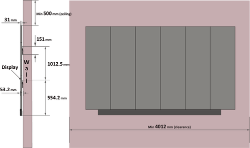 Note:
Note: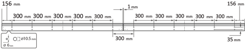


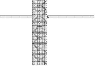 Note:
Note: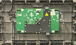
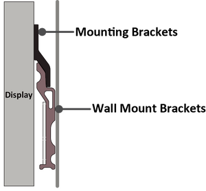
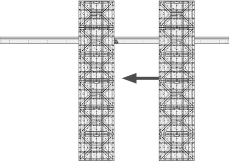 Note: There are 12 screws between each Cabinet.
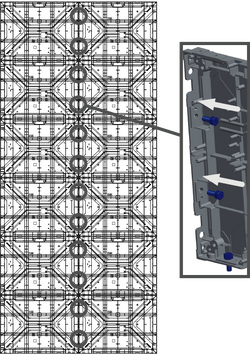
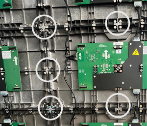
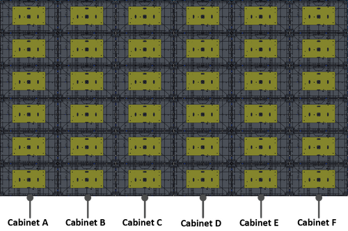

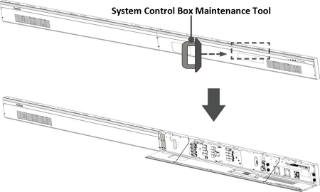

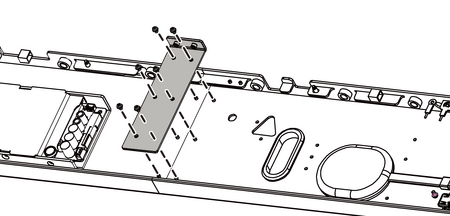
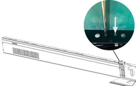

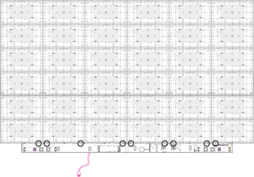
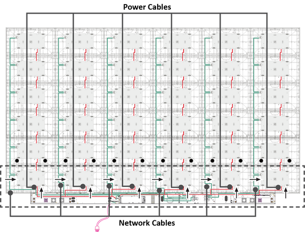

 Note: Ensure that the right speaker is properly connected to the other Audio Out port. See the Introduction section for the position of the LED Display's left and right speakers.
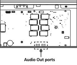
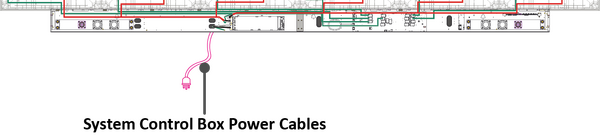
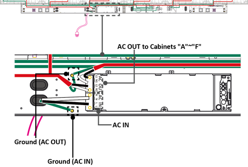
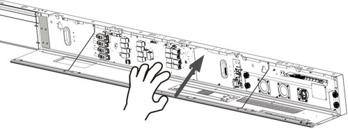
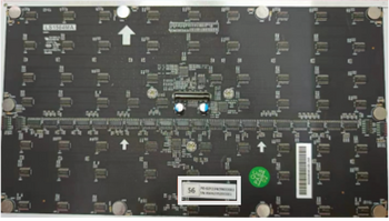
 Note: Before installing the LED Module, ensure that each Module is flush and that there is little to no gap between each. It may be necessary to gently tap the module to make it flush.
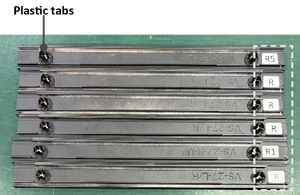


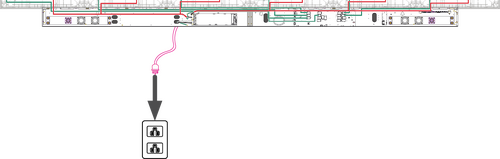 Note: When the System Control Box Power Cables are connected to power outlets, the Power Indicator Light will be a steady red. This means the LED Display is in standby mode. Please refer to the User Guide for more details.
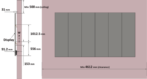 Note:
Note: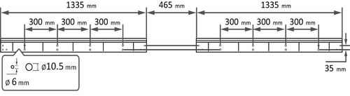

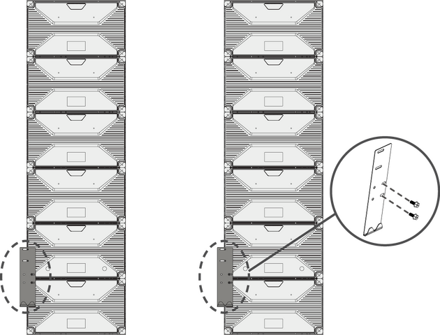 Rear View of Cabinet "D" (left) and Cabinet "B" (right)
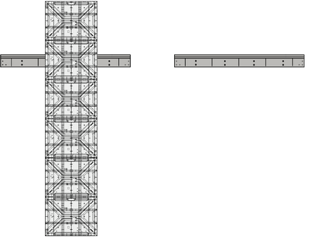
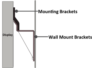
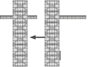 Note: There are 12 screws between each Cabinet.
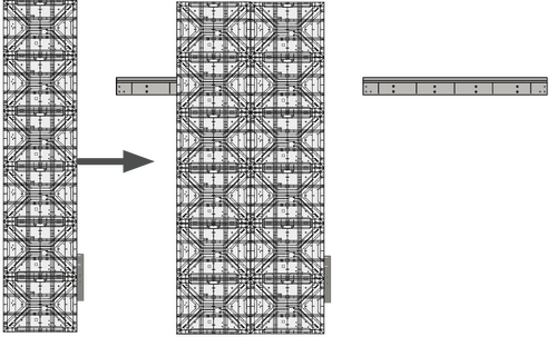
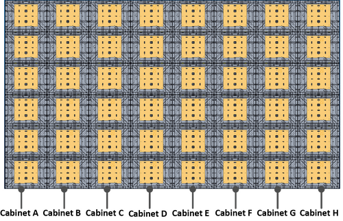
 Power Cable of Cabinet sections "A", "B", and "C"
 Power Cable of Cabinet sections "D", "E", and "F"
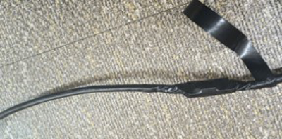
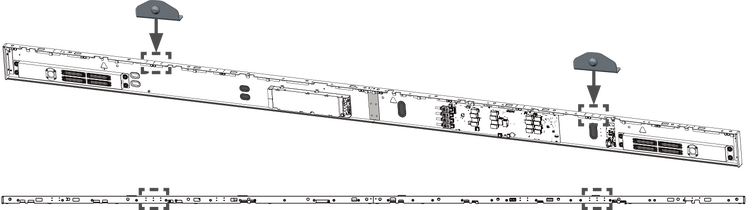 Installing the Lower System Control Box Mount Brackets onto the System Control Box (Front and Top Views)
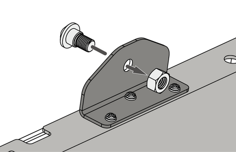 Installing the provided screw and nut to the Brackets (Rear View)
 System Control Box (Front View)
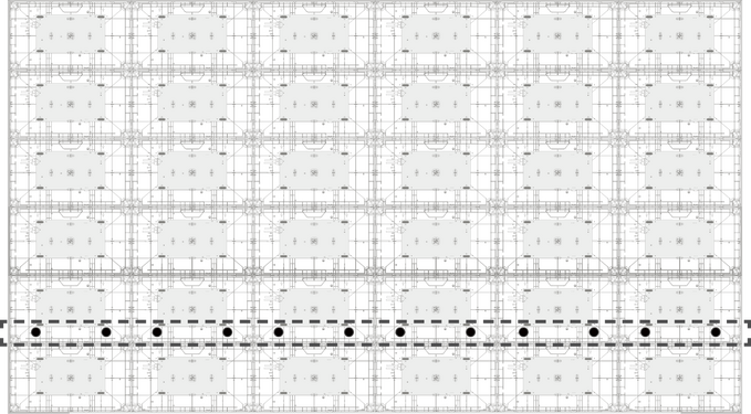 Cabinets (Rear View)
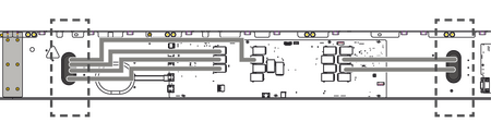
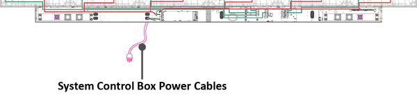

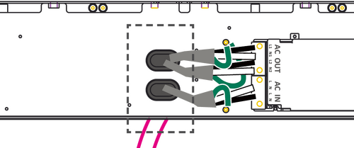

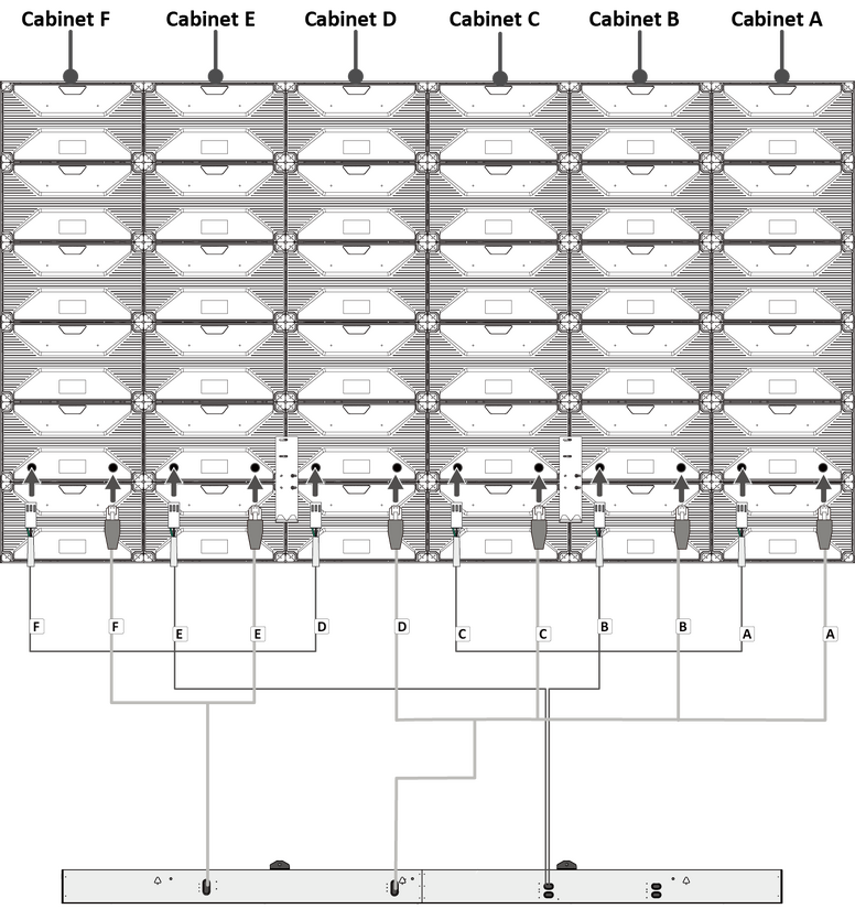 Threading the Power and Network Cables from behind (Rear View)
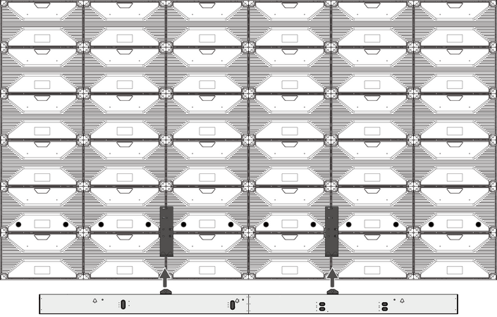 Placing the Lower System Control Box Mount Brackets to the Upper (Rear View)
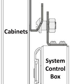
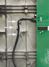

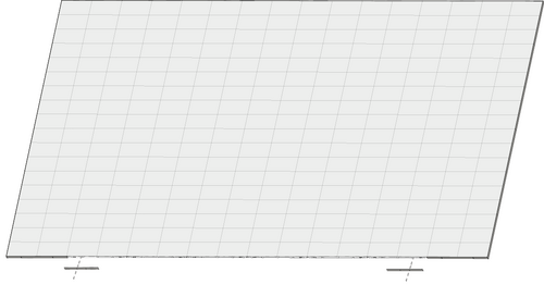
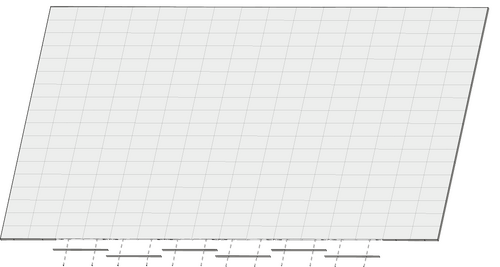
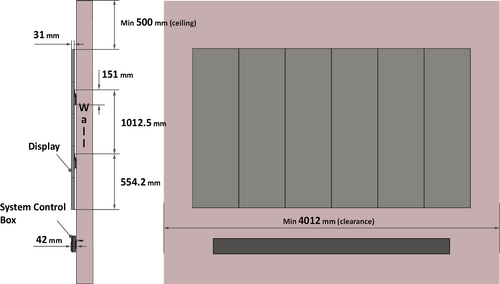 Note:
Note: Drill Hole Spacing for System Control Box
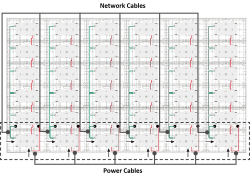

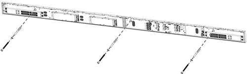

 Left and Right Supports
 Top & Bottom Cross Beams
![Upper Wall Mount Brackets[1]](/images/9/98/LDM163-182_Upper_Wall_Mount_Bracket.svg) Upper Wall Mount Brackets[1]
Upper Wall Mount Brackets[1] Cabinet Brackets
 Nuts and Bolts
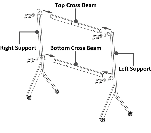 Building the Trolley (Rear View)
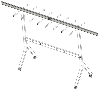
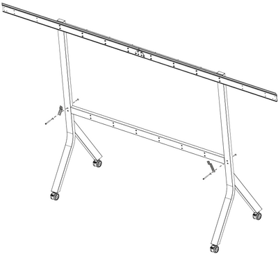
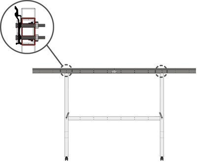
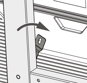
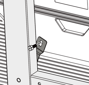
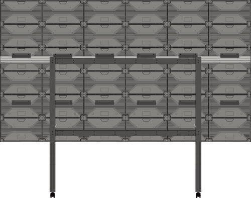


 Note: Other preinstalled-vCast devices in the same network will be listed.
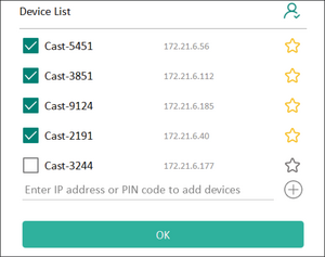 Note:
Note:


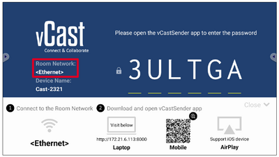

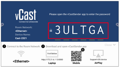


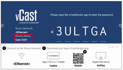


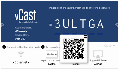


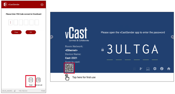


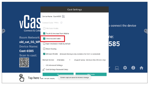
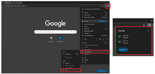


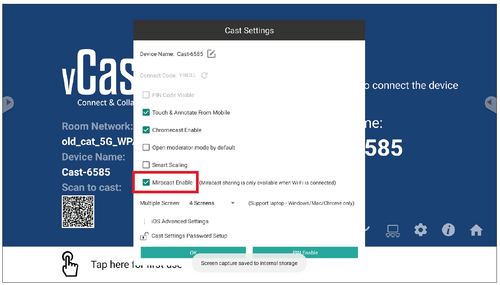
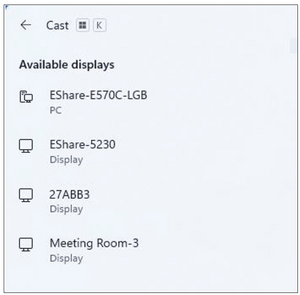
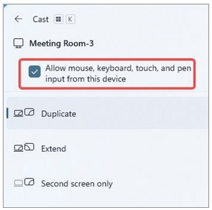


