
IFP55G1 Introduction: Difference between revisions
From ViewSonic Documentation
Tag: visualeditor |
No edit summary |
||
| (42 intermediate revisions by one other user not shown) | |||
| Line 5: | Line 5: | ||
<div class="item1" style="text-align:center; font-size:16; background-color:#DB0025; font-weight:bold; color:#ffffff;">{{PAGENAME}}</div> | <div class="item1" style="text-align:center; font-size:16; background-color:#DB0025; font-weight:bold; color:#ffffff;">{{PAGENAME}}</div> | ||
<div class="grid-item">[[IFP55G1_Introduction|Introduction]] </div> | <div class="grid-item">[[IFP55G1_Introduction|Introduction]] </div> | ||
<div class="grid-item">[[ | <div class="grid-item">[[IFP55G1_Remote_Control|Remote Control]] </div> | ||
<div class="grid-item">[[IFP55G1_Using_Gestures|Using Gestures]]</div> | <div class="grid-item">[[IFP55G1_Using_Gestures|Using Gestures]]</div> | ||
<div class="grid-item">[[IFP55G1_Connecting_Devices|Connecting Devices]]</div> | <div class="grid-item">[[IFP55G1_Connecting_Devices|Connecting Devices]]</div> | ||
<div class="grid-item">[[ | <div class="grid-item">[[IFP55G1_Using_the_ViewBoard|Using the ViewBoard]] </div> | ||
<div class="grid-item">[[IFP55G1_On-Screen Display_Menu_Tree|On-Screen Display Menu Tree]] </div> | |||
<div class="grid-item">[[IFP55G1_On-Screen_Display_Operation|On-Screen Display Menu Operation]] </div> | |||
<div class="grid-item">[[IFP55G1_RS-232_Protocols|RS-232 Protocols]]</div> | <div class="grid-item">[[IFP55G1_RS-232_Protocols|RS-232 Protocols]]</div> | ||
<div class="grid-item">[[IFP55G1_Specifications|Specifications]]</div> | <div class="grid-item">[[IFP55G1_Specifications|Specifications]]</div> | ||
| Line 19: | Line 21: | ||
</div> | </div> | ||
</noinclude> | </noinclude> | ||
=Package Contents= | =Package Contents= | ||
<div> | <div> | ||
| Line 34: | Line 35: | ||
Replacement_Pen_Nib.svg| Replacement Pen Nib x 4 | Replacement_Pen_Nib.svg| Replacement Pen Nib x 4 | ||
IFP52_RS-232.svg| RS-232 Adapter | IFP52_RS-232.svg| RS-232 Adapter | ||
</gallery> | |||
<gallery mode="nolines"> | |||
IFP52_Clamp.svg| Clamp x 5 | IFP52_Clamp.svg| Clamp x 5 | ||
IFPG1_Wall_Munt_Screw.svg| Wall Mount Screws | IFPG1_Wall_Munt_Screw.svg| Wall Mount Screws | ||
IFP50-5_Wall_Mount_Screws.png| Wall Mount Screws (M8 x 25mm x 4) | IFP50-5_Wall_Mount_Screws.png| Wall Mount Screws (M8 x 25mm x 4) | ||
IFP55G1_Camera_Plate.svg| Camera Plate | |||
</gallery> | </gallery> | ||
| Line 49: | Line 52: | ||
! style="font-weight:bold; background-color:#DB0025; color:#ffffff;"| Quantity | ! style="font-weight:bold; background-color:#DB0025; color:#ffffff;"| Quantity | ||
|- | |- | ||
| | | IFP55G1 | ||
| | | 400 x 200 mm | ||
| M8 x 25 mm | | M8 x 25 mm | ||
| 4 | | 4 | ||
| Line 75: | Line 78: | ||
<div class="res-img">[[File:IFP55G1_Rear_View.png|IFP55G1 Rear Panel|500px]]</div> | <div class="res-img">[[File:IFP55G1_Rear_View.png|IFP55G1 Rear Panel|500px]]</div> | ||
==Control Panel | ==Control Panel== | ||
<div class="res-img">[[File:IFP55G1_Control_Panel.png|IFP55G1 Front Control Panel| | <div class="res-img">[[File:IFP55G1_Control_Panel.png|IFP55G1 Front Control Panel|550px]]</div> | ||
{| class="wikitable" style="text-align:center; width:60%; background-color:#ffffff;" | {| class="wikitable" style="text-align:center; width:60%; background-color:#ffffff;" | ||
|- | |- | ||
| Line 83: | Line 86: | ||
! style="font-weight:bold; background-color:#DB0025; color:#ffffff;"| Description | ! style="font-weight:bold; background-color:#DB0025; color:#ffffff;"| Description | ||
|- | |- | ||
| style="font-weight:bold;" | 1 | | style="font-weight:bold;" | '''1''' | ||
|[[File:Icon_Screen_Brightness_Down.png|50px|Screen Brightness - Icon]] | |[[File:Icon_Screen_Brightness_Down.png|50px|Screen Brightness - Icon]] | ||
| style="text-align:left;" |Decrease screen brightness. | | style="text-align:left;" |Decrease screen brightness. | ||
|- | |- | ||
| style="font-weight:bold;" | 2 | | style="font-weight:bold;" | '''2''' | ||
|[[File:Icon_Screen_Brightness_Up.png|50px|Screen Brightness + Icon]] | |[[File:Icon_Screen_Brightness_Up.png|50px|Screen Brightness + Icon]] | ||
| style="text-align:left;" | Increase screen brightness. | | style="text-align:left;" | Increase screen brightness. | ||
|- | |- | ||
| style="font-weight:bold;" | 3 | | style="font-weight:bold;" | '''3''' | ||
|[[File:M1_mini_Plus_Icon_VolumeDown.png|50px|Volumne - Icon]] | |[[File:M1_mini_Plus_Icon_VolumeDown.png|50px|Volumne - Icon]] | ||
| style="text-align:left;" | Decrease the volume. | | style="text-align:left;" | Decrease the volume. | ||
|- | |- | ||
| style="font-weight:bold;" | 4 | | style="font-weight:bold;" | '''4''' | ||
|[[File:M1_mini_Plus_Icon_VolumeUp.png|50px|Volume + Icon]] | |[[File:M1_mini_Plus_Icon_VolumeUp.png|50px|Volume + Icon]] | ||
|style="text-align:left;" | Increase the volume. | |style="text-align:left;" | Increase the volume. | ||
|- | |- | ||
| style="font-weight:bold;" | 5 | | style="font-weight:bold;" | '''5''' | ||
|[[File:Icon_Touch_Screen.png|50px|Touch Screen Icon]] | |[[File:Icon_Touch_Screen.png|50px|Touch Screen Icon]] | ||
|style="text-align:left;" | Disable/Enable the touch screen. | |style="text-align:left;" | Disable/Enable the touch screen. | ||
|- | |- | ||
| style="font-weight:bold;" | 6 | | style="font-weight:bold;" | '''6''' | ||
|[[File:Icon_Control_Panel_Menu.png|50px|IFP55G1 Menu Icon]] | |[[File:Icon_Control_Panel_Menu.png|50px|IFP55G1 Menu Icon]] | ||
| style="text-align:left;" | Launch the Menu system. | | style="text-align:left;" | Launch the Menu system. | ||
|- | |- | ||
|7 | |'''7''' | ||
|[[File:Icon_Power_BK.png|50px|IFP55G1 Menu Icon]] | |[[File:Icon_Power_BK.png|50px|IFP55G1 Menu Icon]] | ||
|style="text-align:left;" | | |style="text-align:left;" | | ||
* Power indicator light. | *Power indicator light. | ||
* Press to turn ON the device. | * Press to turn ON the device. | ||
* Press to turn OFF/ON the display backlight only. | * Press to turn OFF/ON the display backlight only. | ||
| Line 120: | Line 123: | ||
===Front I/O=== | ===Front I/O=== | ||
<div> | <div> | ||
<p> | ====Overview==== | ||
<p>[[File:IFPG1_Front_IO_Panel.png|450px|Front I/O Panel]]</p> | |||
====Front I/O==== | |||
</p> | <p>[[File:IFPG1_Front_IO.png|300px|Front I/O]]</p> | ||
{| class="wikitable" style="text-align:center; width:60%; background-color:#ffffff;" | {| class="wikitable" style="text-align:center; width:60%; background-color:#ffffff;" | ||
|- | |- | ||
! style="font-weight:bold; background-color:#DB0025; color:#ffffff;"| Number | ! style="font-weight:bold; background-color:#DB0025; color:#ffffff;"| Number | ||
! style="font-weight:bold; background-color:#DB0025; color:#ffffff;"| Port | ! style="font-weight:bold; background-color:#DB0025; color:#ffffff; width:15%;"| Port | ||
! style="font-weight:bold; background-color:#DB0025; color:#ffffff;"| Description | ! style="font-weight:bold; background-color:#DB0025; color:#ffffff;"| Description | ||
|- | |- | ||
| Line 146: | Line 149: | ||
|- | |- | ||
| style="font-weight:bold;" | 3 | | style="font-weight:bold;" | 3 | ||
| | |<p>[[File:Remote_Control_Receiver_ViewBoard.png|30px|IFP65G1's Remote Control Receiver]]</p> | ||
| style="text-align:left;" | Remote control receiver | | style="text-align:left;" | Remote control receiver | ||
|- | |- | ||
| style="font-weight:bold;" | 4 | | style="font-weight:bold;" | 4 | ||
| | |<p>[[File:Ambient_Light_Sensor_ViewBoard.png|35px|IFP65G1's Ambient Light Sensor]]</p> | ||
| style="text-align:left;" | Ambient Light Sensor | | style="text-align:left;" | Ambient Light Sensor | ||
|- | |- | ||
|} | |} | ||
</div> | </div> | ||
===Rear and Side I/O=== | ===Rear and Side I/O=== | ||
<div> | <div> | ||
<p> | ====Overview==== | ||
<p>[[File:IFPG1_Rear_IO_Panel.png|450px|Rear I/O Panel]]</p> | |||
</p> | ====Rear I/O==== | ||
<p>[[File:IFP55G1_Rear_IO.png|300px|Rear I/O]]</p> | |||
{| class="wikitable" style="text-align:center; width:60%; background-color:#ffffff;" | {| class="wikitable" style="text-align:center; width:60%; background-color:#ffffff;" | ||
|- | |- | ||
! style="font-weight:bold; background-color:#DB0025; color:#ffffff;"| Number | ! style="font-weight:bold; background-color:#DB0025; color:#ffffff;"| Number | ||
! style="font-weight:bold; background-color:#DB0025; color:#ffffff;"| Port | ! style="font-weight:bold; background-color:#DB0025; color:#ffffff; width:15%;"| Port | ||
! style="font-weight:bold; background-color:#DB0025; color:#ffffff;"| Description | ! style="font-weight:bold; background-color:#DB0025; color:#ffffff;"| Description | ||
|- | |- | ||
| Line 173: | Line 178: | ||
* USB 2.0 standard | * USB 2.0 standard | ||
|- | |- | ||
| style="font-weight:bold;" | | | style="font-weight:bold;" | 2 | ||
| '''RS-232''' | | '''RS-232''' | ||
| style="text-align:left;" |Serial interface; used for mutual transfer of data between devices | | style="text-align:left;" |Serial interface; used for mutual transfer of data between devices | ||
|- | |- | ||
| style="font-weight:bold;" | | | style="font-weight:bold;" | 3 | ||
| '''LAN''' | | '''LAN''' | ||
|Standard RJ45 (10M/100M/1000M) Internet connection interface. Features hub support for network sharing. | | style="text-align:left;" |Standard RJ45 (10M/100M/1000M) Internet connection interface. Features hub support for network sharing. | ||
|- | |- | ||
|} | |} | ||
====Side I/O==== | |||
<p> | <p> | ||
[[File:IFPG1_Side_IO.png|450px|Side I/O]] | [[File:IFPG1_Side_IO.png|450px|Side I/O]] | ||
| Line 190: | Line 195: | ||
|- | |- | ||
! style="font-weight:bold; background-color:#DB0025; color:#ffffff;"| Number | ! style="font-weight:bold; background-color:#DB0025; color:#ffffff;"| Number | ||
! style="font-weight:bold; background-color:#DB0025; color:#ffffff;"| Port | ! style="font-weight:bold; background-color:#DB0025; color:#ffffff; width:15%;"| Port | ||
! style="font-weight:bold; background-color:#DB0025; color:#ffffff;"| Description | ! style="font-weight:bold; background-color:#DB0025; color:#ffffff;"| Description | ||
|- | |- | ||
| style="font-weight:bold;" | 1 | | style="font-weight:bold;" | '''1''' | ||
| VGA | | '''VGA''' | ||
| style="text-align:left;" | External computer video input | | style="text-align:left;" | External computer video input | ||
|- | |- | ||
| style="font-weight:bold;" | | | style="font-weight:bold;" | '''2''' | ||
| AUDIO OUT | | '''AUDIO OUT''' | ||
| style="text-align:left;" | Audio output to an external speaker/headset | | style="text-align:left;" | Audio output to an external speaker/headset | ||
|- | |- | ||
| style="font-weight:bold;" | | | style="font-weight:bold;" | '''3''' | ||
| AUDIO IN | | '''AUDIO IN''' | ||
| style="text-align:left;" | External computer audio input | | style="text-align:left;" | External computer audio input | ||
|- | |- | ||
| | |'''4''' | ||
|USB | |'''USB''' | ||
| | | style="text-align:left;" | | ||
* USB Type A input | * USB Type A input | ||
* USB 3.0 standard | * USB 3.0 standard | ||
* Connect USB devices such as hard disks, keyboard, mouse, etc. | * Connect USB devices such as hard disks, keyboard, mouse, etc. | ||
|- | |- | ||
| style="font-weight:bold;" | | | style="font-weight:bold;" | '''5''' | ||
| TOUCH 1 | | '''TOUCH 1''' | ||
| style="text-align:left;" | | | style="text-align:left;" | | ||
* USB Type B | * USB Type B | ||
* Touch signal output to external computer | * Touch signal output to external computer | ||
* After connection (with an external computer), the device connected to the USB port can directly be used by the external computer | * After connection (with an external computer), the device connected to the USB port can directly be used by the external computer | ||
:'''NOTE:''' Pairs with '''HDMI 1 port.''' | :<small>'''NOTE:''' Pairs with '''HDMI 1 port.'''</small> | ||
|- | |- | ||
| style="font-weight:bold;" | | | style="font-weight:bold;" | '''6''' | ||
| HDMI 1 | | '''HDMI 1''' | ||
| style="text-align:left;" | | | style="text-align:left;" | | ||
*HDMI input | *HDMI input | ||
| Line 227: | Line 232: | ||
*Supports 4K display; HDMI v. 2.0; CEC; ARC | *Supports 4K display; HDMI v. 2.0; CEC; ARC | ||
|- | |- | ||
| style="font-weight:bold;" | | | style="font-weight:bold;" | '''7''' | ||
| HDMI 2 | | '''HDMI 2''' | ||
| style="text-align:left;" | | | style="text-align:left;" | | ||
* HDMI input | * HDMI input | ||
| Line 234: | Line 239: | ||
* Supports 4K display; HDMI v. 2.0; CEC; ARC | * Supports 4K display; HDMI v. 2.0; CEC; ARC | ||
|- | |- | ||
| style="font-weight:bold;" | | | style="font-weight:bold;" | '''8''' | ||
| HDMI 3 | | '''HDMI 3''' | ||
| style="text-align:left;" | | | style="text-align:left;" | | ||
* HDMI input | * HDMI input | ||
| Line 241: | Line 246: | ||
* Supports 4K display; HDMI v. 2.0; CEC; ARC | * Supports 4K display; HDMI v. 2.0; CEC; ARC | ||
|- | |- | ||
| style="font-weight:bold;" | | | style="font-weight:bold;" | '''9''' | ||
| TOUCH 2 | | '''TOUCH 2''' | ||
| style="text-align:left;" | | | style="text-align:left;" | | ||
* USB Type B | * USB Type B | ||
* Touch signal output to external computer | * Touch signal output to external computer | ||
* After connection (with an external computer), the device connected to the USB port can directly be used by the external computer | * After connection (with an external computer), the device connected to the USB port can directly be used by the external computer | ||
:'''NOTE:''' Pairs with '''HDMI 2 and HDMI 3 ports.''' | :<small>'''NOTE:''' Pairs with '''HDMI 2 and HDMI 3 ports.'''</small> | ||
|- | |- | ||
| style="font-weight:bold;" | 10 | | style="font-weight:bold;" | '''10''' | ||
| | |[[File:LDS135-153_COntrol_Panel_USB_Type C.png|40px]] | ||
| style="text-align:left;" | | | style="text-align:left;" | | ||
* C Type Port input | * C Type Port input | ||
| Line 259: | Line 264: | ||
|} | |} | ||
</div> | </div> | ||
{{#seo: | {{#seo: | ||
|title=ViewSonic ViewBoard | |title=ViewSonic ViewBoard | ||
|title_mode=append | |title_mode=append | ||
|keywords=ViewSonic, ViewBoard, IFPG1, Introduction, | |keywords=ViewSonic, ViewBoard, IFPG1, Introduction, IFP55G1, IFP65G1, IFP75G1, IFP86G1 | ||
|description=An introduction to the IFP55G1 ViewBoard. | |description=An introduction to the IFP55G1 ViewBoard. | ||
}} | }} | ||
Latest revision as of 07:04, 23 January 2026
Package Contents
Note: The power cord and video cables included in your package may vary depending on your country. Please contact your local reseller for more information.
-
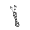 HDMI Cable
(3 m) -
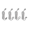 Power Cord
(ship by region) -
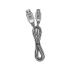 USB Touch Cable (3 m)
 -
 Remote Control
 -
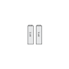 AAA Battery x 2
 -
 Compliance Statement
 -
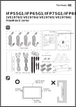 Quick Start Guide
 -
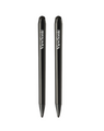 Touch Pen x 2
 -
 Replacement Pen Nib x 4
 -
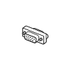 RS-232 Adapter


-
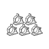 Clamp x 5
 -
 Wall Mount Screws
 -
 Wall Mount Screws (M8 x 25mm x 4)
 -
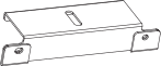 Camera Plate


Wall Mount Kit Specifications (VESA)

| Model | VESA Spec. (A x B) |
Standard Screw (C x D) |
Quantity |
|---|---|---|---|
| IFP55G1 | 400 x 200 mm | M8 x 25 mm | 4 |
NOTE:
- Please follow the instructions in the wall mount installation guide to install your wall mount (check here) or mobile mount bracket (check the video here). If attaching to other building materials, please contact your nearest dealer.
- Do not use screws that are longer than the standard dimension, as they may cause damage to the inside of the display.
Product Overview
Front Panel

Rear Panel

Control Panel

| Number | Item | Description |
|---|---|---|
| 1 | 
|
Decrease screen brightness. |
| 2 | 
|
Increase screen brightness. |
| 3 | 
|
Decrease the volume. |
| 4 | 
|
Increase the volume. |
| 5 | 
|
Disable/Enable the touch screen. |
| 6 | 
|
Launch the Menu system. |
| 7 | 
|
|
I/O Panels
Front I/O
Overview

Front I/O

| Number | Port | Description |
|---|---|---|
| 1 | USB |
|
| 2 | USB |
|
| 3 |
|
Remote control receiver |
| 4 |
|
Ambient Light Sensor |


Rear and Side I/O
Overview

Rear I/O

| Number | Port | Description |
|---|---|---|
| 1 | USB |
|
| 2 | RS-232 | Serial interface; used for mutual transfer of data between devices |
| 3 | LAN | Standard RJ45 (10M/100M/1000M) Internet connection interface. Features hub support for network sharing. |
Side I/O

| Number | Port | Description |
|---|---|---|
| 1 | VGA | External computer video input |
| 2 | AUDIO OUT | Audio output to an external speaker/headset |
| 3 | AUDIO IN | External computer audio input |
| 4 | USB |
|
| 5 | TOUCH 1 |
|
| 6 | HDMI 1 |
|
| 7 | HDMI 2 |
|
| 8 | HDMI 3 |
|
| 9 | TOUCH 2 |
|
| 10 | 
|
|