
IFP65G1 RS-232 Protocols: Difference between revisions
From ViewSonic Documentation
Created page with "<noinclude> <div class="noprint"> <div style="top:1px;width:auto;" class="nomobile"> <div class="grid-container"> <div class="item1" style="text-align:center; font-size:16; background-color:#DB0025; font-weight:bold; color:#ffffff;">{{PAGENAME}}</div> <div class="grid-item">Introduction </div> <div class="grid-item">Remote Control </div> <div class="grid-item">Using Gestures</div> <d..." |
No edit summary |
||
| Line 10: | Line 10: | ||
<div class="grid-item">[[IFP65G1_Using_the_ViewBoard|Using the ViewBoard]] </div> | <div class="grid-item">[[IFP65G1_Using_the_ViewBoard|Using the ViewBoard]] </div> | ||
<div class="grid-item">[[IFP65G1_On-Screen Display_Menu_Tree|On-Screen Display Menu Tree]] </div> | <div class="grid-item">[[IFP65G1_On-Screen Display_Menu_Tree|On-Screen Display Menu Tree]] </div> | ||
<div class="grid-item">[[IFP65G1_On-Screen_Display_Operation|On-Screen Display Operation]] </div> | <div class="grid-item">[[IFP65G1_On-Screen_Display_Operation|On-Screen Display Menu Operation]] </div> | ||
<div class="grid-item">[[IFP65G1_RS-232_Protocols|RS-232 Protocols]]</div> | <div class="grid-item">[[IFP65G1_RS-232_Protocols|RS-232 Protocols]]</div> | ||
<div class="grid-item">[[IFP65G1_Specifications|Specifications]]</div> | <div class="grid-item">[[IFP65G1_Specifications|Specifications]]</div> | ||
Latest revision as of 09:48, 25 June 2024
RS-232
This document describes the hardware interface spec and software protocols of RS-232 interface communication between ViewSonic LFD and PC or other control units with RS-232 protocol.
The protocol contains three command sections:
- Set-Function
- Get-Function
- Remote control pass-through mode
Note: Below, “PC” represents all the control units that can send or receive the RS-232 protocol command.
Description
RS-232 Hardware Specification
ViewSonic LFD communication port on the rear side:
- Connector type: DSUB 9-Pin Male (female or 3.5 mm barrel connector)
- Use of crossover (null modem) cable for connection
- Pin Assignment:
| Pin # | Signal | Remark | |
|---|---|---|---|
| Male DSUB 9-Pin (preferred) | 1 | NC | |
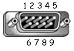 |
2 | RXD | Input to Display |
| 3 | TXD | Output to Display | |
| 4 | NC | ||
| 5 | GND | ||
| Female DSUB 9-Pin | 6 | NC | |
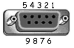 |
7 | NC | |
| 8 | NC | ||
| 9 | NC | ||
| frame | GND |
| Item | Signal | Remark | |
|---|---|---|---|
| 3.5 mm barrel connector (alternative for limited space) |
Tip | TXD | Output from Display |
 |
Ring | RXD | Input to Display |
| Sleeve | GND |
LAN Hardware Specification
ViewSonic LFD communication port on the rear side:
- Connector type: 8P8C RJ45
- Pin assignment:
| Pin # | Signal | Remark | |
|---|---|---|---|
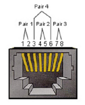 |
1 | TX+ | Output from Display |
| 2 | TX- | Output from Display | |
| 3 | RX+ | Input to Display | |
| 4 | BI_D3+ | For 1G case | |
| 5 | BI_D3- | For 1G case | |
| 6 | RX- | Input to Display | |
| 7 | BI_D4+ | For 1G case | |
| 8 | BI_D4- | For 1G case | |
| frame | GND |
RS-232 Communication Setting
- Baud Rate Select: 9600bps (fixed)
- Data bits: 8 bits (fixed)
- Parity: None (fixed)
- Stop Bits: 1(fixed)
LAN Communication Setting
- Type: Ethernet
- Protocol: TCP/IP
- Port: 7142
- WOL Port: 9 (fixed) for UDP
- Cross subnet: No
- Logon Credentials: No
Command Message Reference
PC sends to LFD command packet followed by “CR”. Every time PC sends control command to Display, the Display shall respond as follows:
- If the message is received correctly it will send “+” (02Bh) followed by “CR” (00Dh)
- If the message is received incorrectly it will send “-” (02Dh) followed by “CR” (00Dh)