VA2932-mhd Initial Setup: Difference between revisions
From ViewSonic Documentation
No edit summary |
|||
| Line 41: | Line 41: | ||
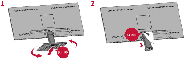
<li>Place the device on a flat, stable surface with the scree facing down.</li> | <li>Place the device on a flat, stable surface with the scree facing down.</li> | ||
<li>Remove the stand.</li> | <li>Remove the stand.</li> | ||
:<div class="res-img">[[File:VA2932-mhd_Wall_Mounting.png| | :<div class="res-img">[[File:VA2932-mhd_Wall_Mounting.png|600px]]</div> | ||
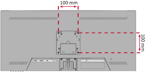
<li>Attach the mounting bracket to the VESA mounting holes at the rear of the monitor. Then secure it with four (4) screws (M4 x 10 mm).</li> | <li>Attach the mounting bracket to the VESA mounting holes at the rear of the monitor. Then secure it with four (4) screws (M4 x 10 mm).</li> | ||
:<div class="res-img">[[File:VA2932-mhd_Wall_Mounting_VESA.png|300px]]</div> | :<div class="res-img">[[File:VA2932-mhd_Wall_Mounting_VESA.png|300px]]</div> | ||
Latest revision as of 08:54, 31 August 2021
Stand Installation

Always place the device on a flat, stable surface. Failure to do so may cause the device to fall and damage the device and/or result in personal injury.
Wall Mounting
Refer to the table below for the standard dimensions for wall mount kits.
For use only with a UL certified wall mount kit/bracket. To obtain a wall-mounting kit or height adjustment base, contact ViewSonic® or your local dealer.
| Maximum Loading | Hole Pattern (W x H) | Interface Pad (W x H x D) | Pad Hole | Screw Specification & Quantity |
|---|---|---|---|---|
| 14 kg | 100 x 100 mm | 115 x 115 x 2.6 mm | Ø 5 mm | M4 x 10 mm - 4 pieces |
- Turn off the device and disconnect all cables.
- Place the device on a flat, stable surface with the scree facing down.
- Remove the stand.
- Attach the mounting bracket to the VESA mounting holes at the rear of the monitor. Then secure it with four (4) screws (M4 x 10 mm).
- Follow the instructions that come with the wall mounting kit to mount the monitor onto the wall.

