
VG2208A Initial Setup: Difference between revisions
From ViewSonic Documentation
Created page with "<noinclude> {{Sticky_Menu_Monitor_2.1 |1=VG2208A_Introduction |2=VG2208A_Initial_Setup |3=VG2208A_Connecting_Power_and_Devices |4=VG2208A_Adjusting_the_Viewing_Angle |5=VG2208A_Quick_Menu |6=VG2208A_Hot_Keys |7=VG2208A_On-Screen_Display_Menu |8=VG2208A_On-Screen_Display_Menu_Tree |9=VG2208A_Specifications |10=VG2208A_Regulatory_and_Service_Information }} </noinclude>" |
|||
| (14 intermediate revisions by the same user not shown) | |||
| Line 13: | Line 13: | ||
}} | }} | ||
</noinclude> | </noinclude> | ||
=Before Installing the Stand= | |||
Please follow the guidelines below when handling the monitor stand. | |||
{{Note|Please make sure that the stand is firmly attached to the monitor before raising it upright, and then remove the bolt.}} | |||
<div class="res-img">[[File:VG2208A_Before_Install.png|600px|alt=safety precautions]]</div> | |||
=Stand Installation= | |||
<div class="res-img">[[File:VG2208A_Install_1.png|500px|alt=Stand installation process]]</div> | |||
{{Note|Always place the device on a flat, stable surface. Failure to do so may cause the device to fall and damage the device and/or result in personal injury.}} | |||
=Wall Mounting= | |||
Refer to the table below for the standard dimensions for mounting kits. | |||
{{Note| | |||
:*For use only with a UL certified mounting kit/bracket. To obtain a wall mounting kit or height adjustment base, contact ViewSonic® or your local dealer. | |||
:*Mounting kits are sold separately. | |||
}} | |||
{| class="wikitable" style="text-align: center; width: 70%; background-color:#ffffff;" | |||
! style="background-color:#DB0025; color:#ffffff;" | Maximum Loading | |||
! style="background-color:#DB0025; color:#ffffff;" | Hole Pattern<br /> (W x H) | |||
! style="background-color:#DB0025; color:#ffffff;" | Interface Pad<br /> (W x H x D) | |||
! style="background-color:#DB0025; color:#ffffff;" | Pad Hole | |||
! style="background-color:#DB0025; color:#ffffff;" | Screw Specification | |||
! style="background-color:#DB0025; color:#ffffff;" | Screw Quantity | |||
|- | |||
|14 kg | |||
|100 x 100 mm | |||
|N/A | |||
|Ø 5 mm | |||
|M4 x 10 mm | |||
|4 screws | |||
|} | |||
<ol> | |||
<li>Turn off the device and disconnect all cables.</li> | |||
<li>Place the device on a flat, stable surface with the screen facing down.</li> | |||
<li> | |||
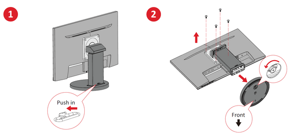
<p>Remove the monitor stand.</p> | |||
<div class="res-img">[[File:VG2208A_Wall_Mount_1.png|600px|alt=monitor hook removeal]]</div> | |||
</li> | |||
<li> | |||
<p>Attach the mounting bracket to the VESA mounting holes at the rear of the device. Then secure it with four screws (M4 x 10 mm).</p> | |||
<div class="res-img">[[File:VG2208A_Wall_Mount_2.png|400px|alt=monitor hook removeal]]</div> | |||
</li> | |||
<li> Follow the instructions that come with the wall mounting kit to mount the monitor.</li> | |||
</ol> | |||
<noinclude> | |||
=Using the Security Slot= | |||
''Please see'' [[Monitor_Security_Slot| Using the Security Slot]]. | |||
</noinclude> | |||
{{#seo: | |||
|title=ViewSonic Monitor | |||
|title_mode=append | |||
|keywords=VG2208A, stand installation, wall mounting, VESA | |||
|description=How to install and uninstall the stand on the VG2208A monitor. | |||
}} | |||
[[Category:VG2208A]] | |||
Latest revision as of 06:30, 2 September 2024
Before Installing the Stand
Please follow the guidelines below when handling the monitor stand.
Note: Please make sure that the stand is firmly attached to the monitor before raising it upright, and then remove the bolt.

Stand Installation

Note: Always place the device on a flat, stable surface. Failure to do so may cause the device to fall and damage the device and/or result in personal injury.
Wall Mounting
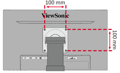
Refer to the table below for the standard dimensions for mounting kits.
Note:
- For use only with a UL certified mounting kit/bracket. To obtain a wall mounting kit or height adjustment base, contact ViewSonic® or your local dealer.
- Mounting kits are sold separately.
| Maximum Loading | Hole Pattern (W x H) |
Interface Pad (W x H x D) |
Pad Hole | Screw Specification | Screw Quantity |
|---|---|---|---|---|---|
| 14 kg | 100 x 100 mm | N/A | Ø 5 mm | M4 x 10 mm | 4 screws |
- Turn off the device and disconnect all cables.
- Place the device on a flat, stable surface with the screen facing down.
-
Remove the monitor stand.
-
Attach the mounting bracket to the VESA mounting holes at the rear of the device. Then secure it with four screws (M4 x 10 mm).
- Follow the instructions that come with the wall mounting kit to mount the monitor.


Using the Security Slot
Please see Using the Security Slot.