From ViewSonic User Guide Database
VB-STND-009 Initial Setup
Assembling the Product
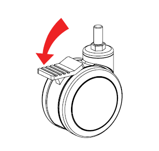
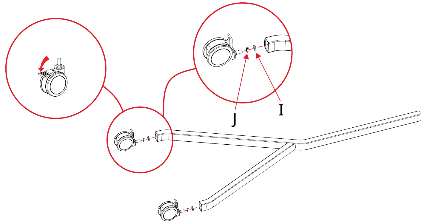
- Engage the break on the wheels of the four Casters (F).
- Screw the four Casters (F) into the Left (A) and Right Trestles (B) using the 20xØ12.5x3.1 mm Spring Washer (J) and 24x12.5x1.5 mm Washer (I).
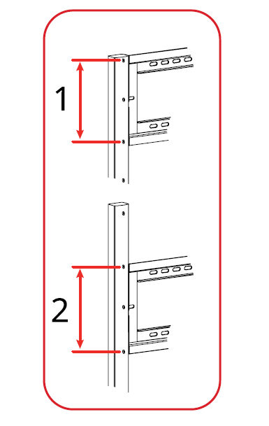
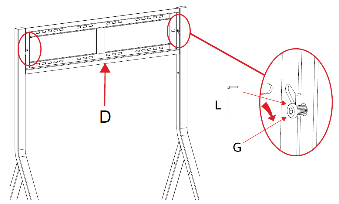
- There are two combinations of mounting holes, on the Left (A) and Right Trestles (B), for the Wall Plate (D).
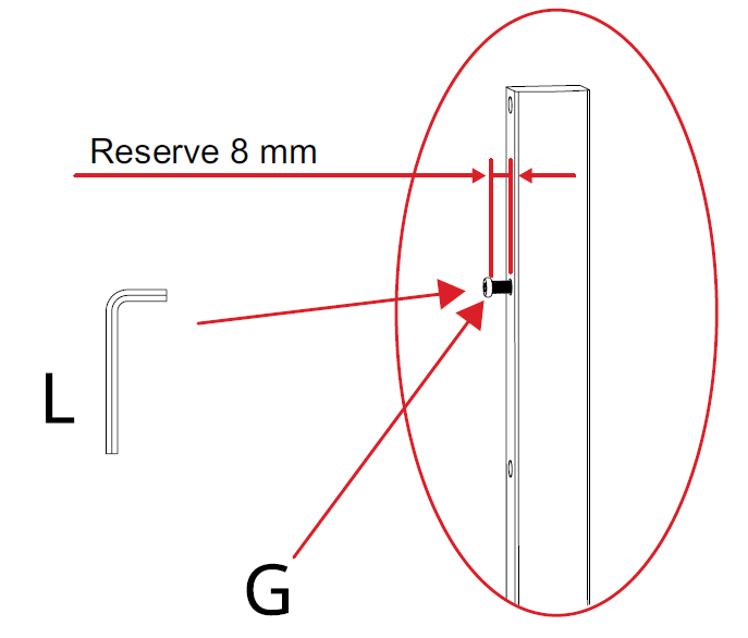
- After choosing the appropriate combination, screw one M8x16 mm Screw (G) halfway into the middle mounting hole of the chosen combination into each Trestle (A & B).
Note: Ensure at least 8 mm of the M8x16 mm Screw (G) is sticking out.
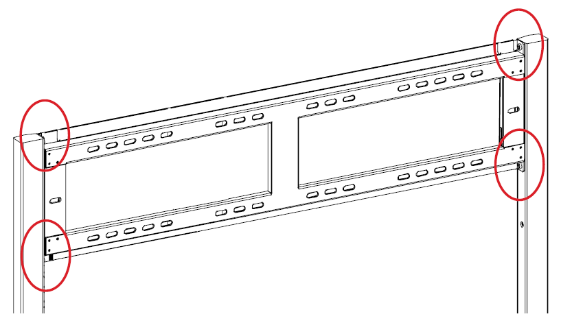
- Hang the Wall Plate (D) onto the two halfway screwed M8x16 mm Screws (G). Once hung, fully tighten both M8x16 mm Screws (G).
- Screw in the remaining four M8x16 Screws (G) to fully secure the Wall Plate (D).
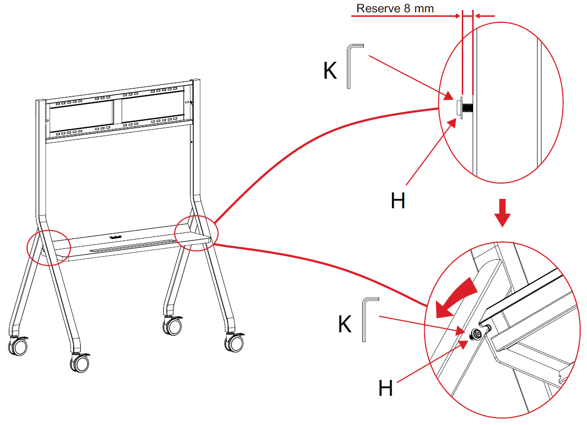
- Screw one M6x12 mm Screw (H) halfway into each Trestle (A & B) as shown below.
Note: Ensure at least 8 mm of the M6x12 mm Screw (H) is sticking out.
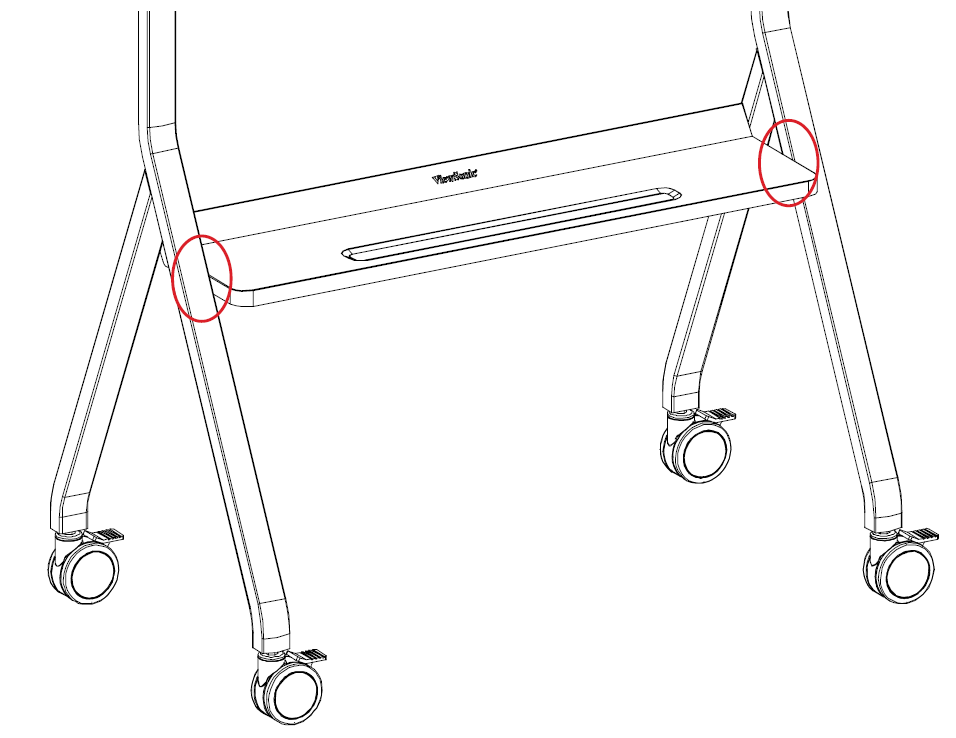
- Place the Storage Tray (C) onto the two exposed M6x12 mm Screws (H). Fully tighten the two M6x12 mm Screws (H). Using the remaining two M6x12 mm Screws (H), further secure the Storage Tray (C) to the Left (A) and Right Trestles (B).
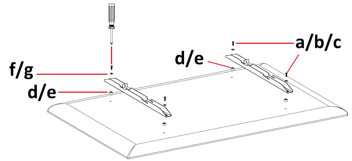
- Secure the two Wall Brackets (E) onto the display as shown below.
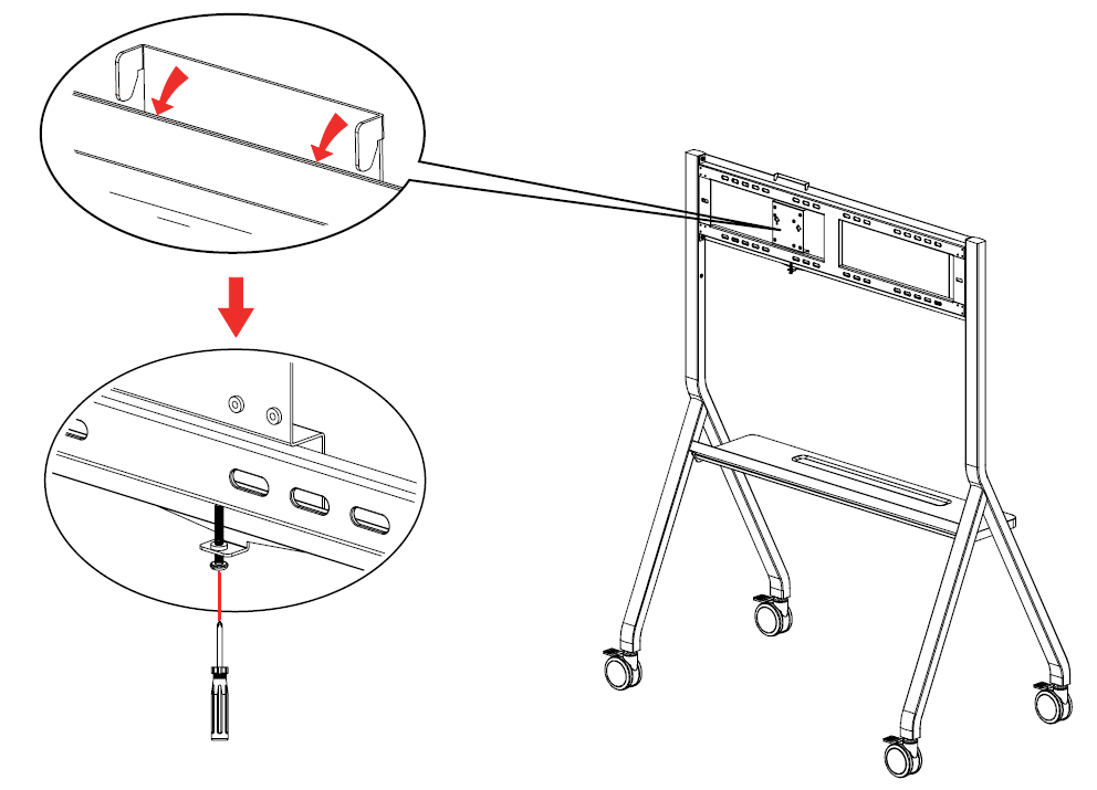
- Secure the Mini PC bracket onto the stand as shown below.
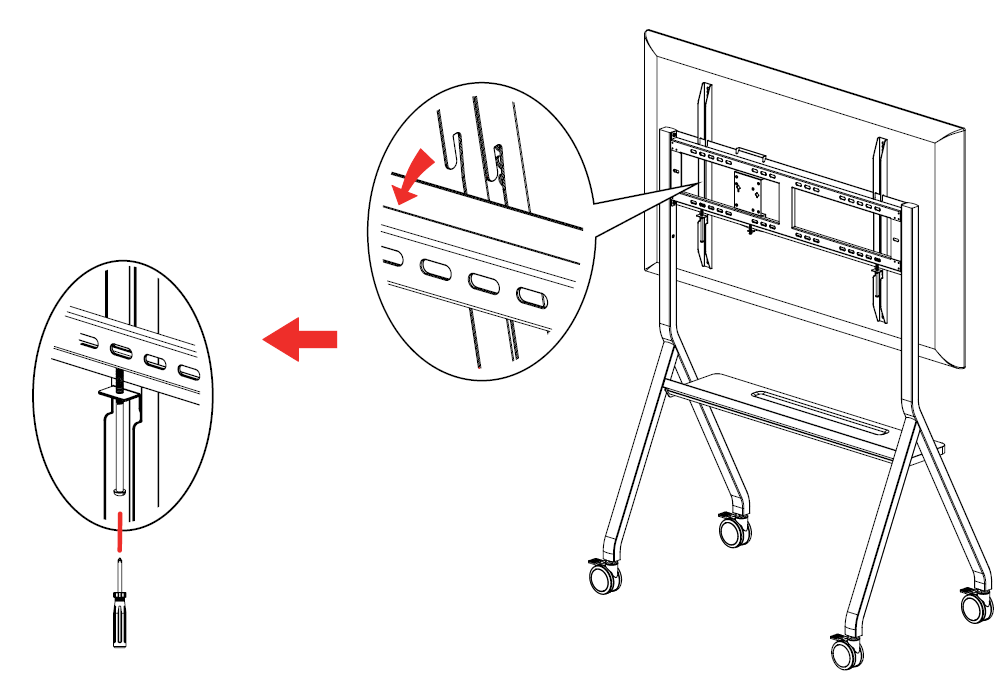
- With two or more people, carefully hang the display, with the Wall Brackets (E) installed, onto the Wall Plate (D). Then lock the safety screws on the Wall Brackets (E).

