IFP8652-2 RS-232 Protocols
RS-232
This document describes the hardware interface spec and software protocols of RS-232 interface communication between ViewSonic LFD and PC or other control units with RS-232 protocol.
The protocol contains three command sections:
- Set-Function
- Get-Function
- Remote control pass-through mode
- NOTE: Below, “PC” represents all the control units that can send or receive the RS-232 protocol command.
Description
RS-232 Hardware Specification
ViewSonic LFD communication port on the rear side:
- Connector type: DSUB 9-Pin Male (female or 3.5 mm barrel connector)
- Use of crossover (null modem) cable for connection
- Pin Assignment:
| Pin # | Signal | Remark | |
|---|---|---|---|
| Male DSUB 9-Pin (preferred) | 1 | NC | |
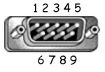 |
2 | RXD | Input to Display |
| 3 | TXD | Output to Display | |
| 4 | NC | ||
| 5 | GND | ||
| Female DSUB 9-Pin | 6 | NC | |
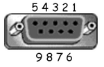 |
7 | NC | |
| 8 | NC | ||
| 9 | NC | ||
| frame | GND |
| Item | Signal | Remark | |
|---|---|---|---|
| 3.5 mm barrel connector (alternative for limited space) |
Tip | TXD | Output from Display |
| Ring | RXD | Input to Display | |
| Sleeve | GND |
LAN Hardware Specification
ViewSonic LFD communication port on the rear side:
- Connector type: 8P8C RJ45
- Pin assignment:
| Pin # | Signal | Remark | |
|---|---|---|---|
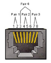 |
1 | TX+ | Output from Display |
| 2 | TX- | Output from Display | |
| 3 | RX+ | Input to Display | |
| 4 | BI_D3+ | For 1G case | |
| 5 | BI_D3- | For 1G case | |
| 6 | RX- | Input to Display | |
| 7 | BI_D4+ | For 1G case | |
| 8 | BI_D4- | For 1G case | |
| frame | GND |
RS-232 Communication Setting
- Baud Rate Select: 9600bps (fixed)
- Data bits: 8 bits (fixed)
- Parity: None (fixed)
- Stop Bits: 1(fixed)
LAN Communication Setting
- Type: Ethernet
- Protocol: TCP/IP
- Port: 5000 (fixed)
- WOL Port: 9 (fixed) for UDP *3.2.0
- Cross subnet: No
- Logon Credentials: No
Command Message Reference
PC sends to LFD command packet followed by “CR”. Every time PC sends control command to Display, the Display shall respond as follows:
- If the message is received correctly it will send “+” (02Bh) followed by “CR” (00Dh)
- If the message is received incorrectly it will send “-” (02Dh) followed by “CR” (00Dh)
Protocol
Set-Function Listing
The PC can control the Display for specific actions. The Set-Function command allows you to control the Display behavior at a remote site through the RS-232 port. The Set-Function packet format consists of 9 bytes.
Set-Function Description
| Length | Total Byte of Message excluding “CR” |
| LFD ID | Identification for each of Display (01~98; default is 01) ID “99” means to apply the set command for all connected displays. Under such circumstances, only ID#1 display has to reply. The LFD ID can be set via the OSD menu for each Display. |
| Command Type | Identify command type, "s" (0x73h): Set Command "+" (0x2Bh): Valid Command Reply "-" (0x2Dh): Invalid Command Reply |
| Command | Function command code: One byte ASCII code. |
| Value [1~3] | Three bytes ASCII that defines the value. |
| CR | 0x0D |
Set-Function Format
Send: (Command Type="s")
| Name | Length | ID | Command Type | Command | Value1 | Value2 | Value3 | CR |
|---|---|---|---|---|---|---|---|---|
| Byte Count | 1 Byte | 2 Byte | 1 Byte | 1 Byte | 1 Byte | 1 Byte | 1 Byte | 1 Byte |
| Bytes Order | 1 | 2~3 | 4 | 5 | 6 | 7 | 8 | 9 |
Reply: (Command Type="+" or "-")
| Name | Length | ID | Command Type | CR |
|---|---|---|---|---|
| Byte Count | 1 Byte | 2 Byte | 1 Byte | 1 Byte |
| Bytes Order | 1 | 2~3 | 4 | 5 |
- NOTE: When PC applies command to all displays (ID=99), only the #1 set needs to reply by the name of ID=1.
Example 1: Set Brightness at 76 for Display (#02) and this; command is valid.
Send (Hex Format)
| Name | Length | ID | Command Type | Command | Value1 | Value2 | Value3 | CR |
|---|---|---|---|---|---|---|---|---|
| Hex | 0x38 | 0x30 0x32 |
0x73 | 0x24 | 0x30 | 0x37 | 0x36 | 0x0D |
Reply (Hex Format)
| Name | Length | ID | Command Type | CR |
|---|---|---|---|---|
| Hex | 0x34 | 0x30 0x32 |
0x2B | 0x0D |
Example 2: Set Brightness at 75 for Display (#02) and this; command is NOT valid.
Send (Hex Format)
| Name | Length | ID | Command Type | Command | Value1 | Value2 | Value3 | CR |
|---|---|---|---|---|---|---|---|---|
| Hex | 0x38 | 0x30 0x32 |
0x73 | 0x24 | 0x30 | 0x37 | 0x35 | 0x0D |
Reply (Hex Format)
| Name | Length | ID | Command Type | CR |
|---|---|---|---|---|
| Hex | 0x34 | 0x30 0x32 |
0x2D | 0x0D |
Set-Function Table
A. Basic Function
| Set Function | Length | ID | Command | Command | Value Range | Comments | |
|---|---|---|---|---|---|---|---|
| Type (ASCII) | Code (ASCII) |
Code (Hex) |
(Three ASCII bytes) | ||||
| Power ON *3.2.1/OFF (Standby) |
8 | s | ! | 21 | 000: STBY 001: ON |
1. The Power-on via LAN control may works only under specific mode. To see display UG for details. *3.1.1
2. “WOL by MAC address” may available as alternative. *3.2.1 | |
| Input Select | 8 | s | " | 22 | 000: TV
001: AV 005: DVI 008: Internal memory 00A: Embedded/Main(Android) |
1. No need for USB
2. For the case of two or more same sources, the 2nd digital is used to indicate the extension. 3. The HEX of 00A is 30 30 41. 4. 00Z is reserved for cycle mode *3.3.1 5. Using 2nd digi to identify DP or Type C. 0 and even numbers stand for DP; odd numbers stand for Type C *3.3.2 | |
| Brightness | 8 | s | $ | 24 | 000 ~ 100 900: Bright down (-1) 901: Bright up (+1) *3.1.1 |
||
| Backlight *3.2.0 | 8 | A | B | 42 | 000~100 | 1. For Android platform whose main mode is controlled by backlight and the other sources are controlled by brightness.
2. Derived from Color calibration. *3.2.0 | |
| Power Lock | 8 | s | 4 | 34 | 000: Unlock 001: Lock |
*See note in details | |
| Volume | 8 | s | 5 | 35 | 000 ~ 100 900: Volume down(-1) 901:Volume up(+1) |
||
| Mute | 8 | s | 6 | 36 | 000: OFF 001: ON (mute) | ||
| Button Lock | 8; | s | 8 | 38 | 000: Unlock 0001: Lock |
*See note in details | |
| Menu Lock | 8 | s | > | 3E | 000: Unlock 001: Lock |
*See note in details | |
| Number *3.1.1 | 8 | s | @ | 40 | 000~009 | ||
| Key Pad *3.1.1 | 8 | s | A | 41 | 000: UP 001: DOWN 002: LEFT 003: RIGHT 004: ENTER 005: INPUT 006: MENU/(EXIT) 007: EXIT | ||
| Remote Control | 8 | s | B | 42 | 000: Disable 001: Enable 002: Pass through |
Disable: RCU will be no function
Enabled: RCU controls normally Pass through: Display will bypass the RC code to connected device via the RS-232 port, but not react itself. | |
| Restore Default | 8 | s | ~ | 7E | 000 | Recover to factory settings | |
NOTE:
1. Behavior at Lock Modes
| Lock Mode | Behavior |
|---|---|
| Button Lock | 1. Lock all buttons on the front panel and RCU, except for “Power” 2. All the SET functions should be workable via RS-232, even the ones with according hot key in RCU like Mute,…etc. |
| MENU Lock | 1. Lock the “MENU’ key of front panel and RCU 2. The Factory and Hospitality modes should not be blocked for the model using MENU-combined key to enter these two modes. Alternative approach will be indicated separately if any limitation by model. |
| POWER Lock | 1. Lock the “POWER” key on the front and RCU. 2. The SET_POWER ON/OFF should be workable via RS-232, but does not mean the POWER lock will be released under this case. 3. Can not be unlocked by reset in OSD setting 4. Will auto AC power-on in power-lock 5. Under power-lock, the set will not enter power saving when no PC signal and neither turn off when no other video signals after 15 minutes. |
| Remote Control Disable | Lock the RCU keys, but keep the front panel buttons workable. |
2. Wake-on-LAN by MAC address as alternative for SET Power on (Length=126 Bytes)
| 6 Bytes | 6 Bytes (#1) | 6 Bytes (#2) | ... | 6 Bytes (#16) | 24 Bytes |
|---|---|---|---|---|---|
| 0xFF FF ... FF | MAC address | MAC address | ... | MAC address | 0x00 00 … 00 |
B. Optional Function
| Set Function | Length | ID | Command | Command | Value Range | Comments | |
|---|---|---|---|---|---|---|---|
| Type (ASCII) | Code (ASCII) |
Code (Hex) |
(Three ASCII bytes) | ||||
| Input Select Cycle *3.3.1 | 8 | s | " | 22 | 00Z | Inputs in cycle loop depend on display itself | |
| Contrast | 8 | s | # | 23 | 000~100 | ||
| Sharpness | 8 | s | % | 25 | 000~100 | ||
| Color | 8 | s | & | 26 | 000~100 | ||
| Tint | 8 | s | ' | 27 | 000~100 | ||
| Backlight On_Off *3.2.3 | 8 | s | ( | 29 | 000: Off 001: On |
Keep both “Backlight On_Off” and “Function On_Off” for backward compatibility *3.3.2 | |
| Color Mode | 8 | s | ) | 29 | 000: Normal 001: Warm 002: Cold 003: Personal |
||
| Freeze On_Off | 8 | s | . | 2A | 000: Off 001: On |
Keep both “Freeze On_Off” and “Function On_Off” for backward compatibility *3.3.2 | |
| Surround sound | 8 | s | - | 2D | 000: Off 001: On |
||
| Bass | 8 | s | . | 2E | 000~100 | ||
| Treble | 8 | s | / | 2F | 000~100 | ||
| Balance | 8 | s | 0 | 30 | 000~100 | 050 is central | |
| Picture Size | 8 | s | 1 | 31 | 000: FULL (16:9) 001: NORMAL (4:3) 002: REAL (1:1) *3.1.0 |
||
| OSD language | 8 | s | 2 | 32 | 000: English 001: French 002: Spanish |
Could be extended for more supported languages by model | |
| PIP-Mode | 8 | s | 9 | 39 | 000: Off 001: PIP(POP) 002: PBP |
||
| PIP-Sound select | 8 | s | : | 3A | 000: Main 001: Sub |
||
| PIP-Position | 8 | s | ; | 3B | 000: Up 001: Down 002: Left 003: Right |
||
| PIP-Input | 8 | s | 7 | 37 *2.9 |
000: TV 005: DVI 007: Slot-in PC (OPS/SDM)/HDBT 00A: Embedded/Main (Android) |
Value range is same as SET-Input select | |
| Tiling-Mode | 8 | s | P | 50 | 000: Off 001: On |
(for video wall) | |
| Tiling-Compensation | 8 | s | Q | 51 | 000: Off 001: On |
(for video wall) Bezel width compensation | |
| Tiling-H by V Monitors | 8 | s | R | 52 | 01x~09x: H 0x1~0x9: V |
(for video wall) 1. 2nd digital for H monitors. 2. 3rd digital for V monitors | |
| Tiling-Position | 8 | s | S | 53 | 001~025 | (for video wall) Copy the screen of Position# to identified display | |
| Date: Year | 8 | s | V | 56 | Y17~Y99 | Last 2 digits (20)17~(20)99 | |
| Date: Month | 8 | s | V | 56 | M01~M12 | 2 digits | |
| Date: Day | 8 | s | V | 56 | D01~D31 | 2 digits | |
| Time: Hour | 8 | s | W | 57 | H00~H23 | 24-hr format. 2 digits. | |
| Time: Min | 8 | s | W | 57 | M00~M59 | 2 digits | |
| Time: Sec | 8 | s | W | 57 | S00~S59 | 2 digits | |
| Customized Hot Keys *3.2.6 | 8 | s | X | 58 |
001~999 |
||
| Function On_Off *3.3.2 | 8 | s | = | 3D |
001: Backlight OFF |
||
NOTE:
1. Tiling definition of H Monitors, V Monitors, and Position

2. Set Date example
| Date: | 2017-3/15 |
| Send: | 0x 38 30 31 73 56 59 31 37 0D (“Y17”) |
| Send: | 0x 38 30 31 73 56 4D 30 33 0D (“M03”) |
| Send: | 0x 38 30 31 73 56 44 31 35 0D (“D15”) |
3. Set Time example
| Time: | 16:27:59 |
| Send: | 0x 38 30 31 73 57 48 31 36 0D (“H16”) |
| Send: | 0x 38 30 31 73 57 4D 32 37 0D (“M27”) |
| Send: | 0x 38 30 31 73 57 53 35 39 0D (“S59”) |
Get-Function Listing
The PC can interrogate the LFD for specific information. The Get-Function packet format consists of 9 bytes which is similar to the Set-Function packet structure. Note that the “Value” byte is always = 000.
Get-Function Description
| Length | Total Byte of Message excluding “CR”. |
| TV/DS ID | Identification for each of TV/DS (01~98; default is 01). |
| Command Type |
Identify command type, |
| Command | Function command code: One byte ASCII code. |
| Value [1~3] | Three bytes ASCII that defines the value. |
| CR | 0x0D |
Get-Function Format
Send: (Command Type=“g”)
| Name | Length | ID | Command Type | Command | Value1 | Value2 | Value3 | CR |
|---|---|---|---|---|---|---|---|---|
| Byte Count | 1 Byte | 2 Byte | 1 Byte | 1 Byte | 1 Byte | 1 Byte | 1 Byte | 1 Byte |
| Bytes Order | 1 | 2~3 | 4 | 5 | 6 | 7 | 8 | 9 |
Reply: (Command Type="r" or "-")
If the Command is valid, Command Type="r"
| Name | Length | ID | Command Type | Command | Value1 | Value2 | Value3 | CR |
|---|---|---|---|---|---|---|---|---|
| Byte Count | 1 Byte | 2 Byte | 1 Byte | 1 Byte | 1 Byte | 1 Byte | 1 Byte | 1 Byte |
| Bytes Order | 1 | 2~3 | 4 | 5 | 6 | 7 | 8 | 9 |
If the Command is NOT valid, Command Type="-"
| Name | Length | ID | Command Type | CR |
|---|---|---|---|---|
| Byte Count | 1 Byte | 2 Byte | 1 Byte | 1 Byte |
| Bytes Order | 1 | 2~3 | 4 | 5 |
Example 1: Get Brightness from TV-05 and this command is valid. The Brightness value is 67.
Send (Hex Format)
| Name | Length | ID | Command Type | Command | Value1 | Value2 | Value3 | CR |
|---|---|---|---|---|---|---|---|---|
| Hex | 0x38 | 0x30 0x35 |
0x67 | 0x62 | 0x30 | 0x30 | 0x30 | 0x0D |
Reply (Hex Format)
| Name | Length | ID | Command Type | Command | Value1 | Value2 | Value3 | CR |
|---|---|---|---|---|---|---|---|---|
| Hex | 0x38 | 0x30 0x35 |
0x72 | 0x62 | 0x30 | 0x36 | 0x37 | 0x0D |
Example 2: Get Color from Display (#05), but the Color command is not supported by this model.
Send (Hex Format)
| Name | Length | ID | Command Type | Command | Value1 | Value2 | Value3 | CR |
|---|---|---|---|---|---|---|---|---|
| Hex | 0x38 | 0x30 0x35 |
0x67 | 0x26 | 0x30 | 0x30 | 0x30 | 0x0D |
Reply (Hex Format)
| Name | Length | ID | Command Type | CR |
|---|---|---|---|---|
| Hex | 0x34 | 0x30 0x35 |
0x2D | 0x0D |
Get-Function Table
A. Basic Function
| Get Function | Length | ID | Command | Command | Response Range | Comments | |
|---|---|---|---|---|---|---|---|
| Type (ASCII) | Code (ASCII) | Code (Hex) | (Three ASCII bytes) | ||||
| Get-Brightness | 8 | g | b | 62 | 000 ~ 100 | ||
| Get-Backlight *3.2.0 | 8 | a | B | 42 | 000 ~ 100 | 1. For Android platform whose main mode is controlled by backlight and the other sources are controlled by brightness. 2. Dervied from Color calibration. *3.2.0 | |
| Get-Volume | 8 | g | f | 66 | 000 ~ 100 | ||
| Get-Mute | 8 | g | g | 67 | 000: OFF 001: ON (muted) |
||
| Get-Input select | 8 | g | j | 6A | 000 ~ 100 | 1. 1st digit for signal dection: 0 means "no signal"; 1 means "signal detected". 2. 2nd & 3rd digit: See Set-Function table. | |
| Get-Power status: ON/STBY | 8 | g | l | 6C | 001: ON 000: STBY |
||
| Get-Remote control | S | g | n | 6E | 000: Disable 001: Enable 002: Pass through |
Get RCU mode status | |
| Get-Power lock | 8 | g | o | 6F | 000: Unlock 001: Lock |
||
| Get-Button lock | 8 | g | p | 70 | 000: Unlock 001: Lock |
||
| Get-Menu lock | 8 | g | l | 6C | 000: Unlock 001: Lock |
||
| Get-ACK | 8 | g | z | 7A | 000 | This command is used to test the communication link. | |
| Get-Thermal | 8 | g | 0 | 30 | 000~100: 0~+100 deg C -01~99: -1~99 deg C |
||
| Get-Operation hour | 8 | g | 1 | 31 | 000 | 1. Accumlated hours in 6-digit integer (000,001~999,999) *3.2.0 2. Can not be reset when FW update and Factory initiation *3.2.2 3. Reply in new 32-byte format *3.2.0 | |
| Get-Device name | 8 | g | 4 | 34 | 000 | Reply in new 32-byte format *3.2.0 | |
| Get-MAC address | 8 | g | 5 | 35 | 000 | (for models with LAN) Reply in new 32-byte format *3.2.0 | |
| Get-IP address *3.2.0 | 8 | g | 6 | 36 | 000 | (for models with LAN) Reply in new 32-byte format *3.2.0 | |
| Get-Serial number *3.2.0 | 8 | g | 7 | 37 | 000 | Reply in new 32-byte format *3.2.0 | |
| Get-FW version *3.2.0 | 8 | g | 8 | 38 | 000 | Reply in new 32-byte format *3.2.0 | |
NOTE:
1. Get Operation Hour example
Assumed the accumulated operation hour is 123,456 hrs
| Send: 0x 38 30 31 67 31 30 30 30 0D (Get Operation hour) | |
| Reply: 0x 32 30 31 72 31 31 32 33 34 35 36 00 00 … 00 00 0D |
2. Get Device Name example
Assumed the device name is CDE-5500
| Send: 0x 38 30 31 67 34 30 30 30 0D (Get Device Name) | |
| Reply: 0x 32 30 31 72 34 43 44 45 2D 35 35 30 30 00 00 … 00 00 0D |
Assumed the device name is “NMP-302#1”
| Send: 0x 38 30 31 67 34 30 30 30 0D (Get Device Name) | |
| Reply: 0x 32 30 31 72 34 4E 4D 50 2D 33 30 32 23 31 00 00 …00 00 0D |
3. Get MAC address example
Assumed the MAC address is 00:11:22:aa:bb:cc
| Send: 0x 38 30 31 67 35 30 30 30 0D (Get MAC add) | |
| Reply: 0x 32 30 31 72 35 30 30 31 31 32 32 61 61 62 62 63 63 00 00…00 00 0D |
4. Get IP address example
Assumed the IP address is 192.168.100.2
| Send: 0x 38 30 31 67 36 30 30 30 0D (Get IP address) | |
| Reply: 0x 32 30 31 72 36 31 39 32 2E 31 36 38 2E 31 30 30 2E 32 00 00…00 000D |
5. Get Serial number example
Assumed the Serial number is ABC180212345
| Send: 0x 38 30 31 67 37 30 30 30 0D (Get Serial number) | |
| Reply: 0x 32 30 31 72 37 41 42 43 31 38 30 32 31 32 33 34 35 00 00…00 00 0D |
6. Get FW version example
Assumed the FW version is 3.02.001
| Send: 0x 38 30 31 67 38 30 30 30 0D (Get FW version) | |
| Reply: 0x 32 30 31 72 38 33 2E 30 32 2E 30 30 31 00 00…00 00 0D |
B. Optional Function
| Get Function | Length | ID | Command | Command | Response Range | Comments | |
|---|---|---|---|---|---|---|---|
| Type (ASCII) | Code (ASCII) | Code (Hex) | (Three ASCII bytes) | ||||
| Get-Contrast | 8 | g | a | 61 | 000 ~ 100 | ||
| Get-Sharpness | 8 | g | c | 63 | 000 ~ 100 | ||
| Get-Color | 8 | g | d | 64 | 000 ~ 100 | ||
| Get-Tint | 8 | g | e | 65 | 000 ~ 100 | ||
| Get-Backlight On_Off *3.2.3 | 8 | g | h | 68 | 000: OFF 001: ON |
Keep both "Backlight On_Off" and "Function On_Off" for backward compatibility *3.3.2 | |
| Get Freeze On_Off *3.2.5 | 8 | g | i | 69 | 000: OFF 001: ON |
Keep both "Freeze On_Off" and "Function On_Off" for backward compatibility *3.3.2 | |
| Get-PIP mode | 8 | g | t | 74 | 000: OFF 001: PIP (POP) 002: PBP |
||
| Get-PIP input | 8 | g | u | 75 | 000 ~ | See "Set-Input select" | |
| Get-Tiling Mode | 8 | g | v | 76 | 000: OFF 001: ON |
(for video wall) | |
| Get-Tiling Compensation | 8 | g | w | 77 | 000:OFF 001: ON |
(for video wall) Bezel width compensation | |
| Get-Tiling H by V monitors | 8 | g | x | 78 | 01x~09x: H monitors 0x1~0x9: V monitors |
(for video wall) 1. 2nd digital for H monitors 2. 3rd digital for V monitors | |
| Get-Tiling position | 8 | g | y | 79 | 000: OFF 001~025 |
(for video wall) Copy the screen of Position# to identified display | |
| Get-Date: Year | 8 | g | 2 | 32 | Y00~Y00 | Last two digits: (20)17~(20)99 | |
| Get-Date: Month | 8 | g | 2 | 32 | M00~M00 | 2 digits | |
| Get-Date: Day | 8 | g | 2 | 32 | D00~D00 | 2 digits | |
| Get-Time: Hour | 8 | g | 3 | 33 | H00~H00 | 24-hr format. 2 digits | |
| Get-Time: Min | 8 | g | 3 | 33 | M00~M00 | 2 digits | |
| Get-Time: Sec | 8 | g | 3 | 33 | S00~S00 | 2 digits | |
| Get-Smart hub *3.3.0 | 8 | g | : | 3A | 000: all 00A: Amb_Temp 00B: Amb_Humidity 00C: Amb_Light 00D: Amb_PIR detection |
1. Reply in new 32-byte format. Each sub-item length is fixed 6 bytes. *3.3.0 2. Allow get data separately or once for all. *3.3.0 | |
| Get-Function On_Off *3.3.2 | 8 | G | = | 3D | 001: Backlight OFF 101: Backlight ON 002: Freeze OFF 102: Freeze ON 003: Touch OFF 103: Touch ON |
||
NOTE:
1. Get Date example
Assumed the current date of display#01 as below:
| Date: | 2017-3/15 |
| Send: | 0x 38 30 31 67 32 59 30 30 0D (Get Date:Year) |
| Reply: | 0x 38 30 31 72 32 59 31 37 0D (“Y17”) |
| Send: | 0x 38 30 31 67 32 4D 30 30 0D (Get Date:Month) |
| Reply: | 0x 38 30 31 72 32 4D 30 33 0D (“M03”) |
| Send: | 0x 38 30 31 67 32 44 30 30 0D (Get Date:Day) |
| Reply: | 0x 38 30 31 72 32 44 31 35 0D (“D15”) |
2. Get Time example
Assumed the current time of display#01 as below:
| Time: | 16:27:59 |
| Send: | 0x 38 30 31 67 33 48 30 30 0D (Get Time:Hour) |
| Reply: | 0x 38 30 31 72 33 48 31 36 0D (“H16”) |
| Send: | 0x 38 30 31 67 33 4D 30 30 0D (Get Time:Min) |
| Reply: | 0x 38 30 31 72 33 4D 32 37 0D (“M27”) |
| Send: | 0x 38 30 31 67 33 53 30 30 0D (Get Time:Sec) |
| Reply: | 0x 38 30 31 72 33 53 35 39 0D (“S59”) |
3. Get Smart hub example
Assumed Amb_Temp is -5 deg C, Amb_Humidity is 30%, Amb_Light is 80, Amb_PIR detection is 1
| Send: | 0x 38 30 31 67 3A 30 30 30 0D (Get all Smart hub info) |
| Reply: | 0x 32 30 31 72 3A 41 2D 30 35 2E 30 42 30 33 30 2E 30 43 30 30 30 38 30 44 30 30 30 30 31 00 00 00 0D (A-05.0B030.0C00080D00001) |
| Send: | 0x 38 30 31 67 3A 30 30 41 0D (Get Amb_Temp only) |
| Reply: | 0x 32 30 31 72 3A 41 2D 30 35 2E 30 00 00 …00 00 0D (A-05.0) |
C. Auto Reply *3.2.2
The display will send out the updated data/status automatically without GET query from the host whenever the following data/status is changed by the user through any of the available ways like: remote control unit, front control panel keys, or touch screen.
- Power On/Off
- Input Select
- Brightness
- Backlight
- Volume
- Mute On/Off
Remote Control Pass-through Mode
When the PC sets the Display to Remote Control Pass through mode, the Display will send a 7-byte packet (followed by “CR”) in response to remote control unit (RCU) button activation.
In this mode the RCU will have no effect on the Display function. For example: “Volume+” will not change the volume of the Display, but instead only send the “Volume+” code to the PC over the RS-232 port.
IR Pass Through-Function format
Reply: (Command Type="p")
| Name | Length | ID | Command Type | RCU Code1 (MSB) |
RCU Code2 (LSB) |
CR |
|---|---|---|---|---|---|---|
| Byte Count | 1 Byte | 2 Byte | 1 Byte | 1 Byte | 1 Byte | 1 Byte |
| Bytes Order | 1 | 2~3 | 4 | 5 | 6 | 7 |
Example 1: Remote Control Pass-through when “VOL+” key is pressed for Display (#5)
Send (Hex Format)
| Name | Length | ID | Command Type | RCU Code1 (MSB) |
RCU Code2 (LSB) |
CR |
|---|---|---|---|---|---|---|
| Hex | 0x36 | 0x30 0x35 |
0x70 | 0x31 | 0x30 | 0x0D |
| Key | Code (HEX) | Basic *3.1.1 | Optional *3.1.1 |
|---|---|---|---|
| 1 | 01 | V | |
| 2 | 02 | V | |
| 3 | 03 | V | |
| 4 | 04 | V | |
| 5 | 05 | V | |
| 6 | 06 | V | |
| 7 | 07 | V | |
| 8 | 08 | V | |
| 9 | 09 | V | |
| 0 | 0A | V | |
| - | 0B | V | |
| RECALL (LAST) | 0C | V | |
| INFO (DISPLAY) | 0D | V | |
| 0E | |||
| ASPECT (ZOOM, SIZE) | 0F | V | |
| VOLUME UP (+) | 10 | V | |
| VOLUME DOWN (-) | 11 | V | |
| MUTE | 12 | V | |
| CHANNEL/PAGE UP (+)/BRIGHTNESS+ | 13 | V | |
| CHANNEL/PAGE DOWN(-)/BRIGHTNESS- | 14 | V | |
| POWER | 15 | V | |
| SOURCES (INPUTS) | 16 | V | |
| 17 | |||
| 18 | |||
| SLEEP | 19 | V | |
| MENU | 1A | V | |
| UP | 1B | V | |
| DOWN | 1C | V | |
| LEFT (-) | 1D | V | |
| RIGHT (+) | 1E | V | |
| OK (ENTER, SET) | 1F | V | |
| EXIT | 20 | V | |
| 21 | |||
| 22 | |||
| 23 | |||
| 24 | |||
| 25 | |||
| 26 | |||
| 27 | |||
| 28 | |||
| 29 | |||
| 2A | |||
| 2B | |||
| RED (F1) | 2C | V | |
| GREEN (F2) | 2D | V | |
| YELLOW (F3) | 2E | V | |
| BLUE (F4) | 2F | V |
NOTE:
1. This IR-pass-through code is different from the RCU key code.
2. Special control sequence for POWER key under IR-pass through mode.
2-1. When Display is OFF and receives the IR POWER code: Display will turn itself ON, then forward the POWER code to the host via RS-232.
2-2. When Display is ON and receives the IR POWER code: Display will forward the POWER code to the host via RS-232, then turn OFF itself.
2-3. When SET-POWER LOCK is enabled, the Display will not respond to POWER key pressing.
3. The VOLUME UP and VOLUME DOWN code will repeatedly output when you press and hold the keys.