CDE7530 RS-232 Protocols
RS-232
This document describes the hardware interface spec and software protocols of RS-232 interface communication between ViewSonic LFD and PC or other control units with RS-232 protocol.
The protocol contains three command sections:
- Set-Function
- Get-Function
- Remote control pass-through mode
- NOTE: Below, “PC” represents all the control units that can send or receive the RS-232 protocol command.
Description
RS-232 Hardware Specification
ViewSonic LFD communication port on the rear side:
- Connector type: DSUB 9-Pin Male (female or 3.5 mm barrel connector)
- Use of crossover (null modem) cable for connection
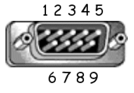
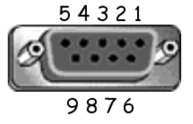
- Pin Assignment:
| Pin # | Signal | Remark | |
|---|---|---|---|
| Male DSUB 9-Pin (preferred) | 1 | NC | |
| 2 | RXD | Input to Display | |
| 3 | TXD | Output to Display | |
| 4 | NC | ||
| 5 | GND | ||
| Female DSUB 9-Pin | 6 | NC | |
| 7 | NC | ||
| 8 | NC | ||
| 9 | NC | ||
| frame | GND |
| Item | Signal | Remark | |
|---|---|---|---|
| 3.5 mm barrel connector (alternative for limited space) |
Tip | TXD | Output from Display |
| Ring | RXD | Input to Display | |
| Sleeve | GND |
LAN Hardware Specification
ViewSonic LFD communication port on the rear side:
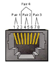
- Connector type: 8P8C RJ45
- Pin assignment:
| Pin # | Signal | Remark | |
|---|---|---|---|
| 1 | TX+ | Output from Display | |
| 2 | TX- | Output from Display | |
| 3 | RX+ | Input to Display | |
| 4 | BI_D3+ | For 1G case | |
| 5 | BI_D3- | For 1G case | |
| 6 | RX- | Input to Display | |
| 7 | BI_D4+ | For 1G case | |
| 8 | BI_D4- | For 1G case | |
| frame | GND |
RS-232 Communication Setting
- Baud Rate Select: 9600bps (fixed)
- Data bits: 8 bits (fixed)
- Parity: None (fixed)
- Stop Bits: 1(fixed)
LAN Communication Setting
- Type: Ethernet
- Protocol: TCP/IP
- Port: 5000 (fixed)
- WOL Port: 9 (fixed) for UDP
- Cross subnet: No
- Logon Credentials: No
Command Message Reference
PC sends to LFD command packet followed by “CR”. Every time PC sends control command to Display, the Display shall respond as follows:
- If the message is received correctly it will send “+” (02Bh) followed by “CR” (00Dh)
- If the message is received incorrectly it will send “-” (02Dh) followed by “CR” (00Dh)
Protocol
Set-Function Listing
The PC can control the Display for specific actions. The Set-Function command allows you to control the Display behavior at a remote site through the RS-232 port. The Set-Function packet format consists of 9 bytes.
Set-Function Description:
| Length | Total Byte of Message excluding “CR” |
| LFD ID | Identification for each of Display (01~98; default is 01) ID “99” means to apply the set command for all connected displays. Under such circumstances, only ID#1 display has to reply. The LFD ID can be set via the OSD menu for each Display. |
| Command Type | Identify command type, "s" (0x73h): Set Command "+" (0x2Bh): Valid Command Reply "-" (0x2Dh): Invalid Command Reply |
| Command | Function command code: One byte ASCII code. |
| Value [1~3] | Three bytes ASCII that defines the value. |
| CR | 0x0D |
Set-Function Format Send: (Command Type="s")
| Name | Length | ID | Command Type | Command | Value1 | Value2 | Value3 | CR |
|---|---|---|---|---|---|---|---|---|
| Byte Count | 1 Byte | 2 Byte | 1 Byte | 1 Byte | 1 Byte | 1 Byte | 1 Byte | 1 Byte |
| Bytes Order | 1 | 2~3 | 4 | 5 | 6 | 7 | 8 | 9 |
Reply: (Command Type="+" or "-")
| Name | Length | ID | Command Type | CR |
|---|---|---|---|---|
| Byte Count | 1 Byte | 2 Byte | 1 Byte | 1 Byte |
| Bytes Order | 1 | 2~3 | 4 | 5 |
- NOTE: When PC applies command to all displays (ID=99), only the #1 set needs to reply by the name of ID=1.
Example 1: Set Brightness as 76 for Display (#02) and this; command is valid.
Send (Hex Format)
| Name | Length | ID | Command Type | Command | Value1 | Value2 | Value3 | CR |
|---|---|---|---|---|---|---|---|---|
| Hex | 0x38 | 0x30 0x32 |
0x73 | 0x24 | 0x30 | 0x37 | 0x36 | 0x0D |
Reply (Hex Format)
| Name | Length | ID | Command Type | CR |
|---|---|---|---|---|
| Hex | 0x34 | 0x30 0x32 |
0x2B | 0x0D |
Example 2: Set Brightness as 75 for Display (#02) and this; command is NOT valid.
Send (Hex Format)
| Name | Length | ID | Command Type | Command | Value1 | Value2 | Value3 | CR |
|---|---|---|---|---|---|---|---|---|
| Hex | 0x38 | 0x30 0x32 |
0x73 | 0x24 | 0x30 | 0x37 | 0x35 | 0x0D |
Reply (Hex Format)
| Name | Length | ID | Command Type | CR |
|---|---|---|---|---|
| Hex | 0x34 | 0x30 0x32 |
0x2D | 0x0D |
Set-Function Table
A. Basic Function
| Set Function | Length | ID | Command | Command | Value Range | Comments | |
|---|---|---|---|---|---|---|---|
| Type (ASCII) | Code (ASCII) |
Code (Hex) |
(Three ASCII bytes) | ||||
| Power On/Off (Standby) |
8 | s | ! | 21 | 000: STBY 001: ON |
1. The Power-on via LAN control may works only under specific mode. To see display UG for details. *3.1.1 2. “WOL by MAC address” may available as alternative.*3.2.1 | |
| Input Select | 8 | s | " | 22 | 004: HDMI 1 014: HDMI 2 024: HDMI 006: VGA 007: Slot-in PC (OPS) 009: DP 019: Type-C 00A: Embedded/Main (Android) |
1. No need for USB 2. For the case of two more same sources, the 2nd digital is used to indicate the extension. 3. The HEX of 00A is 30 30 41. | |
| Brightness | 8 | s | $ | 24 | 000 ~ 100 900: Bright down (-1) 901: Bright up (+1) *3.1.1 |
||
| Backlight*3.2.0 | 8 | A | B | 42 | 000~100 | 1. For Android platform whose main mode is controlled by backlight and the other sources are controlled by brightness. 2. Derived from Color calibration. *3.2.0 | |
| Power Lock | 8 | s | 4 | 34 | 000: Unlock 001: Lock |
*See note in details | |
| Volume | 8 | s | 5 | 35 | 000 ~ 100 900: Volume down(-1) 901:Volume up(+1) |
||
| Mute | 8 | s | 6 | 36 | 000: OFF 001: ON (mute) | ||
| Button Lock | 8; | s | 8 | 38 | 000: Unlock 0001: Lock |
*See note in details | |
| Menu Lock | 8 | s | > | 3E | 000: Unlock 001: Lock |
*See note in details | |
| Number *3.1.1 | 8 | s | @ | 40 | 000~009 | ||
| Key Pad *3.1.1 | 8 | s | A | 41 | 000: UP 001: DOWN 002: LEFT 003: RIGHT 004: ENTER 005: INPUT 006: MENU/(EXIT) 007: EXIT | ||
| Remote Control | 8 | s | B | 42 | 000: Disable 001: Enable 002: Pass through |
Disable: RCU will be no function Enabled: RCU controls normally Pass through: Display will bypass the RC code to connected device via the RS-232 port, but not react itself. | |
| Restore Default | 8 | s | ~ | 7E | 000 | Recover to factory setting | |
B. Optional Function
| Set Function | Length | ID | Command | Command | Value Range | Comments | |
|---|---|---|---|---|---|---|---|
| Type (ASCII) | Code (ASCII) |
Code (Hex) |
(Three ASCII bytes) | ||||
| Contrast | 8 | s | # | 23 | 000~100 | ||
| Sharpness | 8 | s | % | 25 | 000~100 | ||
| Color | 8 | s | & | 26 | 000~100 | ||
| Tint | 8 | s | ' | 27 | 000~100 | ||
| Backlight On_Off | 8 | s | ( | 29 | 000: Off 001: On |
||
| Color Mode | 8 | s | ) | 29 | 000: Normal 001: Warm 002: Cold 003: Personal |
||
| Freeze On_Off | 8 | s | . | 2A | 000: Off 001: On |
||
| Bass | 8 | s | . | 2E | 000~100 | ||
| Treble | 8 | s | / | 2F | 000~100 | ||
| Balance | 8 | s | 0 | 30 | 000~100 | 050 is central | |
| Picture Size | 8 | s | 1 | 31 | 000: FULL (16:9) 001: NORMAL (4:3) 002: REAL (1:1) *3.1.0 |
||
| OSD language | 8 | s | 2 | 32 | 000: English 001: French 002: Spanish |
Could be extended for more supported languages by model | |
| Date: Year | 8 | s | V | 56 | Y17~Y99 | Last 2 digits (20)17~(20)99 | |
| Date: Month | 8 | s | V | 56 | M01~M12 | 2 digits | |
| Date: Day | 8 | s | V | 56 | D01~D31 | 2 digits | |
| Time: Hour | 8 | s | W | 57 | H00~H23 | 24-hr format. 2 digits. | |
| Time: Min | 8 | s | W | 57 | M00~M59 | 2 digits | |
| Time: Sec | 8 | s | W | 57 | S00~S59 | 2 digits | |
| Customized Hot Keys | 8 | s | X | 58 | 001~999 001: Open MVBA app |
||


