TD2465: Difference between revisions
No edit summary |
No edit summary |
||
| Line 1: | Line 1: | ||
__TOC__ | |||
{{:TD2465_Introduction}} | {{:TD2465_Introduction}} | ||
{{:TD2465_Initial_Setup}} | {{:TD2465_Initial_Setup}} | ||
| Line 10: | Line 10: | ||
{{:TD2465_Specifications}} | {{:TD2465_Specifications}} | ||
{{:TD2465_Regulatory_and_Service_Information}} | {{:TD2465_Regulatory_and_Service_Information}} | ||
{{ | <hr> | ||
{{ | {{Customer_Service_Link}} | ||
{{Limited_Warranty_Link}} | |||
=[[Monitor_Safety_Precautions|Safety Precautions]]= | |||
=[[Monitor_Troubleshooting|Troubleshooting]]= | |||
=[[Monitor_Maintenance|Maintenance]]= | |||
{{#seo: | {{#seo: | ||
|title=ViewSonic Touch Monitors | |title=ViewSonic Touch Monitors | ||
Latest revision as of 07:07, 31 December 2025
Package Contents
|
 |
Front View / Rear View
-
 Front View
 -
 Rear View


| Letter | Item |
|---|---|
| A | Display Screen |
| B | Power LED |
| C | Control Panel Keys |
| D | Adjustable Foot |
I/O Ports

| Number | Item |
|---|---|
| 1 | AC IN |
| 2 | DisplayPort |
| 3 | HDMI |
| 4 | VGA |
| 5 | Audio In |
| 6 | Audio Out |
| 7 | USB Upstream |
| 8 | USB Downstream |
Adjusting the Stand
- Place the monitor on a flat, stable surface with the screen facing down.
- With one hand support the monitor, then carefully lift and extend the stand.

- Lift the device into its upright position on a flat, stable surface.

Stand Installation
- Place the monitor on a flat, stable surface with the screen facing down.
- Ensure the Adjustable Foot is secured against the monitor.
- Align the mounting holes of the stand with the VESA mounting holes at the rear of the monitor.
- Secure the stand to the monitor with the screws provided.

- Lift the device into its upright position on a flat stable surface.

Wall Mounting
Refer to the table below for the standard dimensions for wall mount kits.
| Maximum Loading | Hole Pattern (W x H) | Interface Pad (W x H x D) | Pad Hole | Screw Specification | Quantity |
|---|---|---|---|---|---|
| 14 kg | 100 x 100 mm | 115 x 115 x 2.6 mm | Ø 5 mm | M4 x 10 mm | 4 screws |
- Turn off the device and disconnect all cables.
- Place the device on a flat, stable surface with the screen facing down.
- Unscrew the attached stand and carefully remove it.
- Attach the mounting bracket to the VESA mounting holes at the rear of the monitor. Then secure it with four (4) screws (M6 x 12 mm).
- Follow the instructions that come with the wall mounting kit to mount the monitor onto the wall.

Connecting to Power
|
 |
| Connecting to Power |
Connecting External Devices
-
 DisplayPort Connection
 -
 HDMI Connection
 -
 VGA Connection
 -
 USB Connection
 -
 Audio Connection


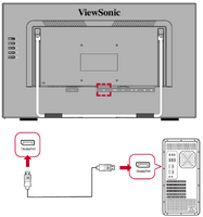
DisplayPort
Connect one end of a DisplayPort cable to the DisplayPort port. Then connect the other end of the cable to the DisplayPort or mini DP port of your computer.
- NOTE: To connect the monitor to the Thunderbolt port (v. 1&2) on your Mac, connect the mini DP end of the “mini DP to DisplayPort cable” to the Thunderbolt output of your Mac. Then connect the other end of the cable to the DisplayPort port of the monitor.
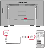
HDMI
Connect one end of an HDMI cable to the HDMI port of your monitor. Then connect the other end of the cable to the HDMI port of your computer.
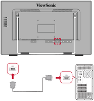
VGA
Connect one end of a VGA cable to the VGA port. Then connect the other end of the cable to the VGA port of your computer.
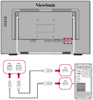
USB
Connect one end of a USB cable to a USB port of the monitor. Then connect the other end of the cable to a USB port of your computer.
USB Number Description Type A Two (2) Connection for your Type A peripheral device(s) (e.g., storage or peripheral device). Type B One (1) Connect the USB Type B male cable (square with 2 cut corners) to this port, and then connect the other end of the cable to the USB downstream port of your computer.
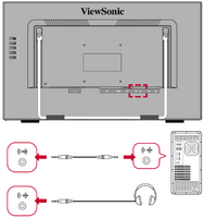
Audio
Plug an audio cable into the Audio In/Audio Out port of the monitor. Plug the other end into your computer (Audio In) or ear-/headphones (Audio Out).
- NOTE: The monitor is also equipped with dual speakers (2W x 2).
Touch Function Control
Before using the touch function, ensure the USB Type B to Type A cable is connected to your computer and the Windows operating system is running.
Your external device(s) can be connected in any of the following configurations:
DisplayPort Connection

- Connect a DisplayPort cable from your computer to the DisplayPort port on the monitor.
- Connect the USB Type A to Type B cable from your computer to the monitor to enable touch controls.
HDMI Connection

- Connect an HDMI cable from your computer to the HDMI port on the monitor.
- Connect the USB Type A to Type B cable from your computer to the monitor to enable touch controls.
VGA Connection

- Connect a VGA cable from your computer to the VGA port on the monitor.
- Connect the USB Type A to Type B cable from your computer to the monitor to enable touch controls.
When using the touch function, please note:
- The touch function may need about five (5) seconds to resume if the USB cable is removed and plugged in again, or the computer resumes from Sleep Mode.
- The touchscreen can only detect up to ten (10) fingers simultaneously.
- If the Windows’ cursor does not accurately follow your finger when you touch the screen, do the following:
- Open: Control Panel > Hardware and Sound >Tablet PC Settings
- Select Calibration.
- Follow the instructions to recalibrate your screen.
If Windows cannot identify the touch screen when you touch the screen, do the following:
- Open: Control Panel > Hardware and Sound > Tablet PC Settings.
- Select Setup > Touch Input.
- Follow the instructions to identify the touch screen.
Adjusting the Viewing Angle
Tilt Angle Adjustment (Adjustable Foot)
Tilt the monitor forwards or backwards to the desired viewing angle (15˚ to 70˚).

Tilt Angle Adjustment (Stand)
Tilt the monitor stand forwards or backwards to the desired viewing angle (-5˚ to 20˚).

- NOTE: When adjusting, support the stand firmly with one hand while tilting the monitor forwards or backwards with the other hand.
Turning the Device On/Off
- Plug the power cord into a power outlet.
- Press the Power key to turn on the monitor.
- To turn the monitor off, press the Power key again.
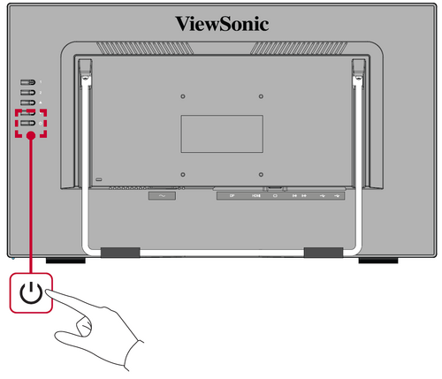
- NOTE: The monitor will still consume some power as long as the power cord is connected to the power outlet. If the monitor is not being used for a long period of time, please disconnect the power plug from the power outlet.

Using the Control Panel Keys
Use the control panel keys to activate Hot Keys, navigate the On-Screen Display (OSD) Menu, and change the settings.

On-Screen Display (OSD) Menu
Press the 1 key to activate the On-Screen Display (OSD) Menu. Follow the key guide that appears on the screen to select options or make adjustments.

| Icon | Name | Description |
|---|---|---|
| Auto Image Adjust | Automatically adjust the screen position. | |
| Contrast/Brightness | Adjust the contrast or brightness level. | |
| Input Select | Select the input source. | |
| Audio Adjust | Adjust the level, or mute the volume. | |
| Color Adjust | Select one of the preset color settings. | |
| Information | Displays the timing mode coming from the graphics card in the computer, the LCD model number, the serial number, and the ViewSonic® website URL. | |
| Manual Image Adjust | Manually set a variety of image quality adjustments. | |
| Setup Menu | Adjust On-Screen Display (OSD) settings. | |
| Memory Recall | Returns the adjustments back to factory settings. |
Hot Keys
When the On-Screen Display (OSD) Menu is off, you can quickly access special functions by using the control panel keys.
| Key | Description |
|---|---|
| 1+▲ | Press and hold the keys to lock/unlock the OSD Menu.
When the menu appears on the screen, continue holding both keys for 10 seconds to lock/unlock the OSD Menu.  If the OSD Menu is locked, the below message will appear on the screen:  |
| 1+▼ | Press and hold the keys to lock/unlock the Power button.
When the menu appears on the screen, continue holding both keys for 10 seconds to lock/unlock the Power button.  If the Power button is locked, the below message will appear on the screen:  |
| 2+▲ | Press the keys to display/hide the boot up screen when the device is turned on.
 |
| 2+▼ | Press the keys to toggle between DDC/CI and DDC/2B.
|
| ▲ | Press the key to enter the Contrast menu. |
| ▼ | Press the key to enter the Color Adjust menu. |
| 2 | Press the key to toggle between input sources. |
General Operation
- Press the 1 key to display the On-Screen Display (OSD) Menu.
- Press the [▲] or [▼] key to select the main menu. Then press the 2 key to enter the selected menu.

- Press the [▲] or [▼] key to select the desired menu option. Then press the 2 key to enter the sub-menu.

- Press the [▲] or [▼] to adjust/select the setting. Then press the 2 key to confirm.

- NOTE: Certain menu option adjustments do not require the user to press the 2 key to confirm the selection. Follow the key guide to select the option or make adjustments.
On-Screen Display (OSD) Menu Tree
| Sub-menu | Menu Option | ||
|---|---|---|---|
| Auto Image Adjust | |||
| Contrast/Brightness | Contrast | (-/+, 0~100) | |
| Brightness | (-/+, 0~100) | ||
| Input Select | VGA | ||
| DisplayPort | |||
| HDMI | |||
| Audio Adjust | Volume | (-/+, 0~100) | |
| Mute | On | ||
| Off | |||
| Audio Input | HDMI | ||
| Audio In | |||
| Color Adjust | sRGB | ||
| Bluish | |||
| Cool | |||
| Native | |||
| Warm | |||
| User Color | Red | (-/+, 0~100) | |
| Green | (-/+, 0~100) | ||
| Blue | (-/+, 0~100) | ||
| Color Space | Auto | ||
| RGB | (-/+, 0~255) | ||
| RGB | (-/+, 16~235) | ||
| YCC | (-/+, 0~255) | ||
| YCC | (-/+, 16~235) | ||
| Information | |||
| Manual Image Adjust | H/V Position | Horizontal Position | (-/+, 0~100) |
| Vertical Position | (-/+, 0~100) | ||
| Horizontal Size | (-/+, 0~100) | ||
| Fine Tune | (-/+, 0~100) | ||
| Sharpness | (-/+, 0~100) | ||
| Dynamic Contrast | On | ||
| Off | |||
| Response Time | Standard | ||
| Advanced | |||
| Ultra Fast | |||
| Aspect Ratio | 4:3 | ||
| Full Screen | |||
| Overscan | On | ||
| Off | |||
| ECO Mode | Standard | ||
| Optimize | |||
| Conserve | |||
| Blue Light Filter | (-/+, 0~100) | ||
| Setup Menu | Language Select | English | |
| Français | |||
| Deutsch | |||
| Español | |||
| Italiano | |||
| Suomi | |||
| Русский | |||
| Türkçe | |||
| 日本語 | |||
| 한국어 | |||
| 繁體中文 | |||
| 简体中文 | |||
| Česká | |||
| Svenska | |||
| Resolution Notice | On | ||
| Off | |||
| OSD Position | H. Position | (-/+, 0~100) | |
| V. Position | (-/+, 0~100) | ||
| OSD Pivot | 0° | ||
| +90° | |||
| -90° | |||
| OSD Timeout | (-/+, 5/15/30/60) | ||
| OSD Background | On | ||
| Off | |||
| Auto Power Off | On | ||
| Off | |||
| Sleep | 30 minutes | ||
| 45 minutes | |||
| 60 minutes | |||
| 120 minutes | |||
| Power Indicator | On | ||
| Off | |||
| Boot Up Screen | On | ||
| Off | |||
| Touch Screen[1] | Single Point Touch | On | |
| Off | |||
| Glove Touch Mode[2] | On | ||
| Off | |||
| Water Resistant Touch Mode[2] | On | ||
| Off | |||
| Touch Disable | On | ||
| Off | |||
| Pen Touch Mode | On | ||
| Off | |||
| Memory Recall | |||
Touch Screen Modes - Additional Information
| Mode | Note |
|---|---|
| Pen Touch Mode |
|
| Glove Touch Mode |
|
| Water Resistant Touch Mode |
|
Technical Specifications
| Item | Category | Specifications |
|---|---|---|
| Model | P/N. | TD2465 |
| No. | VS19150 | |
| LCD | Type | a-Si, TFT Active Matrix 1920 x 1080 LCD,
0.2745 mm x 0.2745 mm pixel pitch |
| Display Size | 60.96 cm, 24" (23.6" viewable) | |
| Surface Treatment | Anti-Glare (Haze 25%), Hard Coating (3H) | |
| Input Signal | Video Sync | RGB Analog (75 Ω)
TMDS Digital (100 Ω)
|
| Compatibility | PC | up to 1920 x 1080 |
| Macintosh | up to 1920 x 1080 | |
| Recommended | 1920 x 1080 @ 60Hz | |
| Resolution[1] | Supported |
|
| Power Adapter[2] | Input Voltage | AC 100-240V, 50/60Hz (auto switch) |
| Display Area | Full Scan (H x V) | 527.04 x 296.46 mm (20.75” x 11.67”) |
| Operating Conditons | Temperature | 0° C to 40° C (32° F to 104° F) |
| Humidity | 20% to 90% (non-condensing) | |
| Altitude | 16,404 feet (4.9 km) | |
| Storage Conditions | Temperature | -20° C to 60° C (-4° F to 140° F) |
| Humidity | 5% to 90% (non-condensing) | |
| Altitude | 40, 000 feet (12.1 km) | |
| Dimensions (with stand) |
Physical (W x H x D) |
549.8 x 400.6 x 197.9 mm (21.6” x 15.8” x 7.8”) |
| Dimensions (without stand) |
Physical (W x H x D) |
549.8 x 325.9 x 49.4 mm (21.6” x 12.8” x 1.9”) |
| Wall Mount | Dimensions | 100 x 100 mm |
| Weight | Physical | 5.69 kg (12.54 lbs) |
| Power Saving Modes | On | 24W (Typical) |
| Off | ≤ 0.3W (Max) |
Compliance Information
This section addresses all connected requirements and statements regarding regulations. Confirmed corresponding applications shall refer to nameplate labels and relevant markings on the unit.
FCC Compliance Statement
This device complies with part 15 of FCC Rules. Operation is subject to the following two conditions: (1) this device may not cause harmful interference, and (2) this device must accept any interference received, including interference that may cause undesired operation. This equipment has been tested and found to comply with the limits for a Class B digital device, pursuant to part 15 of the FCC Rules.
These limits are designed to provide reasonable protection against harmful interference in a residential installation. This equipment generates, uses, and can radiate radio frequency energy, and if not installed and used in accordance with the instructions, may cause harmful interference to radio communications. However, there is no guarantee that interference will not occur in a particular installation. If this equipment does cause harmful interference to radio or television reception, which can be determined by turning the equipment off and on, the user is encouraged to try to correct the interference by one or more of the following measures:
- Reorient or relocate the receiving antenna.
- Increase the separation between the equipment and receiver.
- Connect the equipment into an outlet on a circuit different from that to which the receiver is connected.
- Consult the dealer or an experienced radio/TV technician for help.
Warning: You are cautioned that changes or modifications not expressly approved by the party responsible for compliance could void your authority to operate the equipment.
Industry Canada Statement
CAN ICES-003(B) / NMB-003(B)
CE Conformity for European Countries
| The device complies with the EMC Directive 2014/30/EU and Low Voltage Directive 2014/35/EU. |
The following information is only for EU-member states:
| The mark shown to the right is in compliance with the Waste Electrical and Electronic Equipment Directive 2012/19/EU (WEEE). The mark indicates the requirement NOT to dispose of the equipment as unsorted municipal waste, but use the return and collection systems according to local law. |
Declaration of RoHS2 Compliance
This product has been designed and manufactured in compliance with Directive 2011/65/EU of the European Parliament and the Council on restriction of the use of certain hazardous substances in electrical and electronic equipment (RoHS2 Directive) and is deemed to comply with the maximum concentration values issued by the European Technical Adaptation Committee (TAC) as shown below.
| Substance | Proposed Maximum Concentration | Actual Concentration |
|---|---|---|
| Lead (Pb) | 0.1% | < 0.1% |
| Mercury (Hg) | 0.1% | < 0.1% |
| Cadmium (Cd) | 0.01% | < 0.01% |
| Hexavalent Chromium (Cr6⁺) | 0.1% | < 0.1% |
| Polybrominated biphenyls (PBB) | 0.1% | < 0.1% |
| Polybrominated diphenyl ethers (PBDE) | 0.1% | < 0.1% |
| Bis (2-ethylhexyl) phthalate (DEHP) | 0.1% | < 0.1% |
| Butyl benzyl phthalate (BBP) | 0.1% | < 0.1% |
| Dibutyl phthalate (DBP) | 0.1% | < 0.1% |
| Diisobutyl phthalate (DIBP) | 0.1% | < 0.1% |
Certain components of products as stated above are exempted under the Annex III of the RoHS2 Directives as noted below. Examples of exempted components are:
- Copper alloy containing up to 4% lead by weight.
- Lead in high melting temperature type solders (i.e. lead-based alloys containing 85% by weight or more lead).
- Electrical and electronic components containing lead in a glass or ceramic other than dielectric ceramic in capacitors, e.g. piezoelectronic devices, or in a glass or ceramic matrix compound.
- Lead in dielectric ceramic in capacitors for a rated voltage of 125 V AC or 250 V DC or higher.
Indian Restriction of Hazardous Substances
Restriction on Hazardous Substances statement (India). This product complies with the “India E-waste Rule 2011” and prohibits use of lead, mercury, hexavalent chromium, polybrominated biphenyls or polybrominated diphenyl ethers in concentrations exceeding 0.1 weight % and 0.01 weight % for cadmium, except for the exemptions set in Schedule 2 of the Rule.
Product Disposal at End of Product Life
ViewSonic® respects the environment and is committed to working and living green. Thank you for being part of Smarter, Greener Computing. Please visit the ViewSonic® website to learn more.
USA & Canada:
https://www.viewsonic.com/us/go-green-with-viewsonic
Europe:
https://www.viewsonic.com/eu/environmental-social-governance/recycle
Taiwan:
https://recycle.moenv.gov.tw/
For EU users, please contact us for any safety/accident issue experienced with this product:
| ViewSonic Europe Limited Haaksbergweg 75 1101 BR Amsterdam Netherlands | |
| +31 (0) 650608655 | |
| EPREL@viewsoniceurope.com | |
| https://www.viewsonic.com/eu/ |
Copyright Information
Copyright© ViewSonic® Corporation, 2022. All rights reserved.
Macintosh and Power Macintosh are registered trademarks of Apple Inc.
Microsoft, Windows, and the Windows logo are registered trademarks of Microsoft Corporation in the United States and other countries.
ViewSonic®, the three birds logo, OnView, ViewMatch, and ViewMeter are registered trademarks of ViewSonic® Corporation.
VESA is a registered trademark of the Video Electronics Standards Association. DPMS, DisplayPort, and DDC are trademarks of VESA.
Disclaimer: ViewSonic® Corporation shall not be liable for technical or editorial errors or omissions contained herein; nor for incidental or consequential damages resulting from furnishing this material, or the performance or use of this product.
In the interest of continuing product improvement, ViewSonic® Corporation reserves the right to change product specifications without notice. Information in this document may change without notice.
No part of this document may be copied, reproduced, or transmitted by any means, for any purpose without prior written permission from ViewSonic® Corporation.
TD2465_UG_ENG_1a_20220713