VX3218C-2K Initial Setup: Difference between revisions
From ViewSonic Documentation
| (One intermediate revision by the same user not shown) | |||
| Line 23: | Line 23: | ||
:{{Note-yellow|For use only with a UL certified wall mount kit/bracket. To obtain a wall-mounting kit or height adjustment base, contact ViewSonic® or your local dealer.}} | :{{Note-yellow|For use only with a UL certified wall mount kit/bracket. To obtain a wall-mounting kit or height adjustment base, contact ViewSonic® or your local dealer.}} | ||
{| class="wikitable" style="text-align: center;" | {| class="wikitable" style="text-align: center; background-color:#ffffff; width:auto;" | ||
|- | |- | ||
! style="background-color:# | ! style="background-color:#DB0025; color:#ffffff;"|Maximum Loading | ||
! style="background-color:# | ! style="background-color:#DB0025; color:#ffffff;"|Hole Pattern (W x H) | ||
! style="background-color:# | ! style="background-color:#DB0025; color:#ffffff;"|Interface Pad (W x H x D) | ||
! style="background-color:# | ! style="background-color:#DB0025; color:#ffffff;"|Pad Hole | ||
! style="background-color:# | ! style="background-color:#DB0025; color:#ffffff;"|Screw Specification | ||
! style="background-color:#DB0025; color:#ffffff;"|Quantity | |||
|- | |- | ||
|14 kg | |14 kg | ||
| Line 35: | Line 36: | ||
|115 x 115 x 2.6 mm | |115 x 115 x 2.6 mm | ||
|Ø 5 mm | |Ø 5 mm | ||
|M4 x 10 mm | |M4 x 10 mm | ||
|4 screws | |||
|} | |} | ||
<ol><li>Turn off the device and disconnect all cables.</li> | <ol><li>Turn off the device and disconnect all cables.</li> | ||
<li>Place the device on a flat, stable surface with the scree facing down.</li> | <li>Place the device on a flat, stable surface with the scree facing down.</li> | ||
Latest revision as of 03:01, 31 March 2023
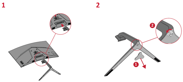
Stand Installation

Always place the device on a flat, stable surface. Failure to do so may cause the device to fall and damage the device and/or result in personal injury.
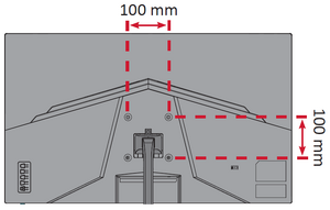
Wall Mounting
Refer to the table below for the standard dimensions for wall mount kits.
For use only with a UL certified wall mount kit/bracket. To obtain a wall-mounting kit or height adjustment base, contact ViewSonic® or your local dealer.
| Maximum Loading | Hole Pattern (W x H) | Interface Pad (W x H x D) | Pad Hole | Screw Specification | Quantity |
|---|---|---|---|---|---|
| 14 kg | 100 x 100 mm | 115 x 115 x 2.6 mm | Ø 5 mm | M4 x 10 mm | 4 screws |
- Turn off the device and disconnect all cables.
- Place the device on a flat, stable surface with the scree facing down.
- Remove the stand.
- Attach the mounting bracket to the VESA mounting holes at the rear of the monitor. Then secure it with four (4) screws (M4 x 10 mm).
- Follow the instructions that come with the wall mounting kit to mount the monitor onto the wall.

