VP2468A
Package Contents
- Monitor
- Power cord
- Video cable
- Quick start guide
Front View / Rear View
-
 Front View
 -
 Rear View


| Letter | Item |
|---|---|
| A | Display Screen |
| B | Control Panel Keys |
| C | Power Button |
| D | Security Slot |
I/O Ports

| Number | Item |
|---|---|
| 1 | AC IN |
| 2 | HDMI |
| 3 | DisplayPort In |
| 4 | USB Type C |
| 5 | DisplayPort Out |
| 6 | Audio Out |
| 7 | USB Type A Port (Downstream) |
| 8 | LAN |
Stand Installation
- Place the monitor on a flat, stable surface with the screen facing down.
- Align and connect the two (2) points on the monitor stand’s base with the monitor stand’s neck.
- Use the captured screw in the monitor stand’s base and secure it to the monitor stand’s neck.
- Lift the device into its upright position on a flat, stable surface.


Wall Mounting
Refer to the table below for the standard dimensions for wall mount kits.
| Maximum Loading | Hole Pattern (W x H) | Interface Pad (W x H x D) | Pad Hole | Screw Specification & Quantity |
|---|---|---|---|---|
| 14 kg | 100 x 100 mm | 115 x 115 x 2.6 mm | Ø 5 mm | M4 x 10 mm - 4 pieces |
- Turn off the device and disconnect all cables.
- Place the device on a flat, stable surface with the screen facing down.
- Remove the four (4) screws.
- Pull down slightly to disengage the hooks and remove the stand.
- Attach the mounting bracket to the VESA mounting holes at the rear of the monitor. Then secure it with four (4) screws (M4 x 10 mm).
- Follow the instructions that come with the wall mounting kit to mount the monitor onto the wall.


Using the Security Slot
To help prevent the device from being stolen, use a security slot locking device to secure the device to a fixed object.
Additionally, fastening the monitor to a wall or fixed object using a security cable can help support the weight of the monitor in order to prevent the monitor from falling over.
Below is an example of setting up a security slot locking device on a table.

Connecting to Power

- Connect the power cord to the AC IN jack at the rear of the device.
- Connect the power cord plug to a power outlet.
Connecting External Devices
-
 HDMI Connection
 -
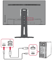
 DisplayPort Connection
 -
 USB Connection
 -
 Audio Connection
 -
 Ethernet Connection


HDMI
Connect one end of an HDMI cable to the HDMI port of your monitor. Then connect the other end of the cable to the HDMI port of your computer.
- NOTE: The monitor is equipped with one HDMI 1.4 port.
DisplayPort
Connect one end of a DisplayPort cable to the DisplayPort port. Then connect the other end of the cable to the DisplayPort or mini DP port of your computer.
- NOTE: To connect the monitor to the Thunderbolt port (v. 1&2) on your Mac, connect the mini DP end of the “mini DP to DisplayPort cable” to the Thunderbolt output of your Mac. Then connect the other end of the cable to the DisplayPort port of the monitor.
USB
Connect one end of a USB cable to a USB port of the monitor. Then connect the other end of the cable to a USB port of your computer.
USB Number Description Type A Two (2) Connection for your Type A peripheral device(s). (e.g. storage device). - NOTE: To use some peripherals, please ensure your computer is also connected to the monitor’s USB Type B port.
Type C One (1) Make sure your Type C output device and cable support video signal transmission.
Audio
Plug the audio jack of the ear-/headphones into the Audio Out port of the monitor. Additionally, you can connect the monitor to a sound bar using an audio cable.
Ethernet
Connect one end of your LAN (RJ45) cable to the LAN (RJ45) port of the monitor. Then connect the other end to your network.
Next, you must connect your computer by:
- Type C connection

DisplayPort/USB Type-C MST Daisy Chain Connection
With DisplayPort/USB Type-C Multi-Stream Transport (MST) support, you can daisy chain connect up to four (4) monitors.
- Connect one end of a DisplayPort/USB Type-C cable to the DisplayPort/USB Type-C Out port of your computer. Then connect the other end of the cable to the DisplayPort In/USB Type-C port of the monitor.
- Use another DisplayPort cable to connect to the DisplayPort Out port of the first monitor. Then connect the other end of the cable to the DisplayPort In port of the second monitor.
- Repeat Step 2 as needed with up to four (4) monitors.
- NOTE: Your graphics card compatibility will determine the number of monitors


- NOTE:
- The max resolution is 1920 x 1080.
- DisplayPort 1.2 MST must be turned on in the Setup Menu in the OSD Menu to do daisy chaining.
- If the input source changes to HDMI, DisplayPort 1.2 MST will turn off automatically.
-
 Height Adjustment
 -
 Swivel Adjustment
 -
 Tilt Angle Adjustment


Height Adjustment
Lower or raise the monitor to the desired height (0 to 130 mm).
- NOTE: When adjusting, press down firmly along the adjustment track holding the monitor with both hands on the side.
Swivel Adjustment
Swivel the monitor to the left or right for the desired viewing angle (60˚).
Tilt Angle Adjustment
Tilt the monitor forwards or backwards to the desired viewing angle (-5˚ to 21˚).
- NOTE: When adjusting, support the stand firmly with one hand while tilting the monitor forwards or backwards with the other hand.
Screen Orientation Adjustment (Monitor Pivot)
-
 Screen Orientation Adjustment
 -
 Screen Orientation Adjustment
 -
 Screen Orientation Adjustment


- Adjust the monitor height to the highest position. Then tilt the monitor backwards to the full tilt position.
- Rotate the monitor 90° clockwise or counter clockwise from landscape to portrait orientation.
- NOTE:
- When adjusting, make sure to hold both sides of your monitor firmly with both hands.
- If using the Auto Pivot function, the system can detect the screen orientation automatically.
Using the Control Panel Keys
Use the control panel keys to access the Quick Access Menu, navigate the On-Screen Display (OSD) Menu, and change the settings.

Quick Menu
Touch the 1/2/3/4 key to activate the Quick menu. Follow the key guide that appears on the screen to select options or make adjustments.

-
 Standard Color
 -
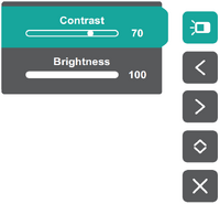 Contrast / Brightness
 -
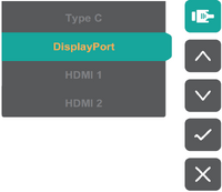 Input Select
 -
 Main Menu


| Icon | Name | Description |
|---|---|---|
| Standard Color | Select one of the preset standard color settings. | |
| Contrast / Brightness | Adjust the contrast or brightness. | |
| Input Select | Select the input source. | |
| Main Menu | Enter the On-Screen Display (OSD) Menu. | |
| Exit | Exit the Quick Menu. |
Hot Keys
When the On-Screen Display (OSD) Menu is off, you can quickly access special functions by using the control panel keys.
| Key | Description |
|---|---|
| 1 | Press and hold the key for 5 seconds to select User mode. Then select the desired User mode to activate.
 |
| 2+3 | Press and hold the keys to lock/unlock the OSD Menu.
When the menu appears on the screen, continue holding both keys for 10 seconds to lock/unlock the OSD Menu.  |
| 2+4 | Press and hold the keys to lock/unlock the Power button.
When the menu appears on the screen, continue holding the key for 10 seconds to lock/unlock the Power button.  |
| 3+5 | Press the keys to display/hide the boot up screen when the device is turned on.
 |
General Operation
- Press the 1/2/3/4 key to display the Quick Menu. Then press the 4 key to display the OSD Menu.
- Press the 1 or 2 key to select the main menu. Then press the 3 key to enter the selected menu.

- Press the 1 or 2 key to select the desired menu option. Then press the 3 key to enter the sub-menu.

- Press the 1 or 2 key to adjust/select the setting. Then press the 3 key to confirm.

- NOTE: Certain menu option adjustments do not require the user to press the 3 key to confirm the selection. Follow the key guide that appears on the bottom of the screen to select the option or make adjustments.
- Press the 4 key to return to the previous menu.
OSD Tree
Input Select
| Sub-menu | Menu Option | |
|---|---|---|
| Type C | ||
| DisplayPort | ||
| HDMI | ||
| Auto Detect | On | |
| Off | ||
Audio Adjust
| Sub-menu | Menu Option | |
|---|---|---|
| Volume | (-/+, 0~100) | |
| Mute | On | |
| Off | ||
ViewMode
| Sub-menu | Menu Option | ||
|---|---|---|---|
| Off | |||
| Game | FPS 1 |
||
| FPS 2 | |||
| RTS | |||
| MOBA | |||
| Movie | |||
| Web | |||
| Text | |||
| MAC | Ultra Clear | (-/+, 0~10) | |
| Photographer | Retro | Ultra Clear | (-/+, 0~10) |
| Advanced-Sharpness | (-/+, 0/25/50/75/100) | ||
| Advanced-Gamma | (-/+, 1/8/2.0/2.2/2.4/2.6) | ||
| Photo | Ultra Clear | (-/+, 0~10) | |
| Advanced-Sharpness | (-/+, 0/25/50/75/100) | ||
| Advanced-Gamma | (-/+, 1/8/2.0/2.2/2.4/2.6) | ||
| TruTone | (-/+, 0~100) | ||
| Landscape | Ultra Clear | (-/+, 0~10) | |
| Advanced-Sharpness | (-/+, 0/25/50/75/100) | ||
| Advanced-Gamma | (-/+, 1/8/2.0/2.2/2.4/2.6) | ||
| TruTone | (-/+, 0~100) | ||
| Portrait | Ultra Clear | (-/+, 0~10) | |
| Advanced-Sharpness | (-/+, 0/25/50/75/100) | ||
| Advanced-Gamma | (-/+, 1/8/2.0/2.2/2.4/2.6) | ||
| TruTone | (-/+, 0~100) | ||
| Skin Tone | (-/+, 0~10) | ||
| Black Stabilization | (-/+, 0~10) | ||
| Monochrome | Advanced-Sharpness | (-/+, 0/25/50/75/100) | |
| TruTone | (-/+, 0~100) | ||
Color Adjust
| Sub-menu | Menu Option | |||
|---|---|---|---|---|
| Contrast/Brightness | Contrast | (-/+, 0~100) | ||
| Brightness | (-/+, 0~100) | |||
| Color Format | Auto | |||
| RGB (Full Range) | ||||
| RGB (Limited Range) | ||||
| YUV (Full Range) | ||||
| YUV (Limited Range) | ||||
| Standard Color | sRGB | |||
| REC 709 | ||||
| DICOM SIM | ||||
| Color Calibration | CAL 1 | |||
| CAL 2 | ||||
| CAL 3 | ||||
| Color Calibration Notice | Remind Schedule Hour | |||
| Counter Hour | ||||
| Recall | ||||
| Custom | Color Temperature | Panel Default | ||
| Bluish | ||||
| Cool | ||||
| Native | ||||
| Warm | ||||
| User | ||||
| Gamma | Off | |||
| 1.8 | ||||
| 2.0 | ||||
| 2.2 | ||||
| 2.4 | ||||
| 2.6 | ||||
| Black Stabilization | (-/+, 0~10) | |||
| Advanced DCR | (-/+, 0/25/50/75/100) | |||
| Gain | Red | (-/+, 0~100) | ||
| Green | (-/+, 0~100) | |||
| Blue | (-/+, 0~100) | |||
| Offset | Red | (-/+, 0~100) | ||
| Green | (-/+, 0~100) | |||
| Blue | (-/+, 0~100) | |||
| Hue | Red | (-/+, 0~100) | ||
| Green | (-/+, 0~100) | |||
| Blue | (-/+, 0~100) | |||
| Cyan | (-/+, 0~100) | |||
| Magenta | (-/+, 0~100) | |||
| Yellow | (-/+, 0~100) | |||
| Saturation | Red | (-/+, 0~100) | ||
| Green | (-/+, 0~100) | |||
| Blue | (-/+, 0~100) | |||
| Cyan | (-/+, 0~100) | |||
| Magenta | (-/+, 0~100) | |||
| Yellow | (-/+, 0~100) | |||
| Recall | ||||
Manual Image Adjust
| Sub-menu | Menu Option |
|---|---|
| Sharpness | (-/+, 0/25/50/75/100) |
| Aspect Ratio | 1:1 |
| 4:3 | |
| Full Screen | |
| Overscan | On |
| Off | |
| Low Input Lag | Off |
| Advanced | |
| Ultra Fast | |
| Response Time | Standard |
| Advanced | |
| Ultra Fast | |
| Blue Light Filter | (-/+, 0~100) |
| Uniformity | On |
| Off |
Setup Menu
| Sub-menu | Menu Option | |||
|---|---|---|---|---|
| Language Select | English | |||
| Français | ||||
| Deutsch | ||||
| Español | ||||
| Italiano | ||||
| Suomi | ||||
| Русский | ||||
| Türkçe | ||||
| 日本語 | ||||
| 한국어 | ||||
| 繁體中文 | ||||
| 简体中文 | ||||
| Česká | ||||
| Svenska | ||||
| Resolution Notice | On | |||
| Off | ||||
| Information | ||||
| OSD Timeout | (-/+, 5/15/30/60) | |||
| OSD Background | On | |||
| Off | ||||
| OSD Pivot | Auto | |||
| 0° | ||||
| +90° | ||||
| -90° | ||||
| 180° | ||||
| Power Indicator | On | |||
| Off | ||||
| Auto Power Off | On | |||
| Off | ||||
| Sleep | 30 minutes | |||
| 45 minutes | ||||
| 60 minutes | ||||
| 120 minutes | ||||
| Off | ||||
| ECO Mode | Standard | |||
| Optimize | ||||
| Conserve | ||||
| DisplayPort 1.2 | On | |||
| Off | ||||
| DDC/CI | On | |||
| Off | ||||
| Save As | User 1 | |||
| User 2 | ||||
| User 3 | ||||
| Recall | ||||
| All Recall | ||||
Input Select

Audio Adjust
| Menu Option | Description |
|---|---|
| Volume | Adjust the volume level. |
| Mute | Enable this option to temporarily turn off the sound. |
ViewMode
| Menu Option | Description |
|---|---|
| Off | Disable the function. |
| Game | Select this option for playing games. |
| Movie | Select this option for watching movies. |
| Web | Select this option for surfing the web. |
| Text | Select this option for text-based tasks. |
| MAC | Select this option when connecting to Mac computers. |
| Photographer | Select this option for viewing photo files. |
Color Adjust
| Menu Option | Description |
|---|---|
| Contrast/Brightness | Contrast
Adjust the degree of difference between the lightest and darkest parts of the picture and change the amount of black and white in the image. |
| Brightness
Adjust the background black levels of the screen image. | |
| Color Format | The monitor can detect the input signal color format automatically. You can manually change the color format options to fit the correct color format range if the colors are not displayed correctly.
|
| Standard Color | The monitor comes with several display industry color standards. Each color mode can be selected for various applications of the monitor.
|
| Color Calibration | Calibrate the monitor using the ViewSonic® Colorbration application with specific color sensors.
|
| Custom | Color Temperature
Select the color temperature setting.
|
| Gamma
Manually adjust the brightness level of the monitor’s grayscale levels. | |
| Black Stabilization
Provide heightened visibility and detail by brightening dark scenes. | |
| Advanced DCR
Automatically detects the image signal and intelligently controls the backlight brightness and color, to improve on the ability to make the black blacker in a dark scene, and make the white whiter in a bright environment. | |
| Gain
Adjust white temperature to customize your User Color (can be saved in User Mode) or a specific color temperature and gain value (red, green, blue). | |
| Offset
Adjust black levels for red, green, and blue. The gain and offset functions allow users to control the white balance for the upmost control when manipulating contrast and dark scenes. | |
| Hue
Adjust the tint of each color (red, green, blue, cyan, magenta, and yellow). | |
| Saturation
Adjust the color depth of each color (red, green, blue, cyan, magenta, and yellow). | |
| Recall
Restore the Custom related settings to default. |
Manual Image Adjust
| Menu Option | Description |
|---|---|
| Sharpness | Adjust the picture quality. |
| Aspect Ratio | Select the aspect ratio of the monitor. |
| Overscan | Automatically enlarge the original picture horizontally and vertically to an equal aspect ratio that fills the screen. |
| Low Input Lag | Select the appropriate speed to decrease input to output latency. |
| Response Time | Adjusts the response time, creating smooth images without streaking, blurring, or ghosting. |
| Blue Light Filter | Adjusts the filter that blocks high-energy blue light for a more comfortable viewing experience. |
| Uniformity | Compensate any luminance and color uniformity imbalances on the screen, such as dark spots, uneven brightness, or illegible images on the screen. |
Setup Menu
| Menu Option | Description |
|---|---|
| Language Select | Select an available language for the OSD Menu. |
| Resolution Notice | Enable this option to allow the system to inform users that the current viewing resolution is not the correct native resolution. |
| Information | Display the monitor information. |
| OSD Timeout | Set the length of time the OSD Menu remains on screen. |
| OSD Background | Show/Hide the OSD background when the OSD Menu appears on the screen. |
| OSD Pivot | Set the OSD Menu orientation.
|
| Power Indicator | Set the Power Indicator On or Off. If the setting is set to On, the power indicator lights blue when the device is turned on. |
| Auto Power Off | Enable this option to allow the monitor to automatically turn off after a certain amount of time. |
| Sleep | Set the amount of idle time before the monitor enters Sleep mode. |
| ECO Mode | Choose between various modes, based on power consumption. |
| DisplayPort 1.2 | Enable DisplayPort 1.2 support. |
| DDC/CI | Enable this option to allow the monitor control via the graphics card. |
| Save As | Set the personalized OSD configurations for User 1/User 2/User 3. |
| All Recall | Resets all settings to their default values. |
Auto Pivot
With the Auto Pivot function, the monitor can detect the image display and adjust the image’s orientation on the screen automatically when pivoting the screen vertically or horizontally.
- NOTE: The Auto Pivot function uses DDC/CI to communicate with the monitor. Before applying the Auto Pivot function, please make sure the DDC/CI setting is set to On.

To enable the DDC/CI setting:
- Open the OSD Menu and select the Setup Menu menu. Then press the 3 key to enter the menu.
- Press the 1 or 2 key to select DDC/CI. Then press the 3 key to enter its sub-menu.
- Press the 1 or 2 key to select On. Then press the 3 key to confirm.
After ensuring DDC/CI is On, proceed to set OSD Pivot to Auto:
- Open the OSD Menu and select the Setup Menu menu. Then press the 3 key to enter the menu.
- Press the 1 or 2 key to select OSD Pivot. Then press the 3 key to enter its submenu.
- Press the 1 or 2 key to select Auto. Then press the 3 key to confirm.
Colorbration+
To ensure long-term color accuracy, some specific models support the hardware color calibration function. The Colorbration+ application installation file can be found at: http://color.viewsonic.com/support/software/.
Standard monitor packing does not include the color sensor, which the Colorbration+ application needs for the calibration process.
Compatible color sensors include:
- X-Rite i1 Display Pro
- X-Rite i1 Pro 2
- X-Rite i1 Studio
- Xrite Colormunki Photo
- Xrite Colormunki Design
- Datacolor Spyder 5
- Datacolor SpyderX series
Colorblindness Mode
Through the vDisplayManager software, this display supports two Color Blindness modes:
- Color Filter
- Simulation
Users who are color blind can activate the Color Filter feature to better see on-screen details.

Designers can activate the Simulation feature to review their designs and verify they look color blind friendly.

NOTE: The vDisplayManager software can be downloaded at: https://color.viewsonic.com/support/software/
Firmware Update
For the best display performance and to resolve any known issues, it is best to keep your monitor updated with the latest firmware version. With the supplied USB cable and the vDisplayManager application, you can easily update your monitor’s firmware.
To update the firmware:

- Download and install the vDisplayManager application: https://color.viewsonic.com/support/software/.
- Connect the USB Type C cable to the USB Type C port of your monitor. Then connect the other end of the cable to the USB port of the computer.
- Launch vDisplayManager. Select the Advanced tab in the side menu.
- Click Update to check for any updates to your monitor’s firmware.
- Wait until the update process is complete (if applicable).
- NOTE: Any interruptions during the firmware update process may permanently damage your monitor. Do not disconnect the USB cable or turn off your PC and monitor.
Technical Specifications

| Model No. | P/N |
|---|---|
| VS16475 | VP2468a |
| Item | Category | Specifications |
|---|---|---|
| LCD | Type | IPS Type, a-si TFT LCD,
Active Matrix 1920 x 1080 0.2745 mm x 0.2745 mm pixel pitch |
| Display Size | 60.47 cm, 24" (23.8" viewable) | |
| Color Filter | RGB vertical stripe | |
| Glass Surface | Anti-Glare type, 3H hard coating | |
| Input Signal | Video Sync | TMDS digital (100 Ω)
|
| Compatibility | PC | up to 1920 x 1080 |
| Macintosh | up to 1920 x 1080 | |
| Recommended | 1920 x 1080 @ 60Hz | |
| Resolution[1] | Supported |
|
| Power Adapter[2] | Input Voltage | AC 100-240V, 50/60Hz (auto switch) |
| Display Area | Full Scan
(H x V) |
527.04 x 296.46 mm
(20.75” x 11.67”) |
| Operating Conditons | Temperature | 0° C to 40° C (32° F to 104° F) |
| Humidity | 20% to 90% (non-condensing) | |
| Altitude | 16,404 feet (4.9 km) | |
| Storage Conditions | Temperature | -20° C to 60° C (-4° F to 140° F) |
| Humidity | 5% to 90% (non-condensing) | |
| Altitude | 40, 000 feet (12.1 km) | |
| Dimensions | Physical
(W x H x D) |
538.67 x 519.48 x 215 mm
(21.21” x 20.45” x 8.46”) |
| Wall Mount | Dimensions | 100 x 100 mm |
| Weight | Physical | 5.88 kg (12.96 lbs) |
| Power Saving Modes | On[3] | 13.9W (Typical) |
| Off | < 0.3W (Max) |
Compliance Information
This section addresses all connected requirements and statements regarding regulations. Confirmed corresponding applications shall refer to nameplate labels and relevant markings on the unit.
FCC Compliance Statement
This device complies with part 15 of FCC Rules. Operation is subject to the following two conditions: (1) this device may not cause harmful interference, and (2) this device must accept any interference received, including interference that may cause undesired operation. This equipment has been tested and found to comply with the limits for a Class B digital device, pursuant to part 15 of the FCC Rules.
These limits are designed to provide reasonable protection against harmful interference in a residential installation. This equipment generates, uses, and can radiate radio frequency energy, and if not installed and used in accordance with the instructions, may cause harmful interference to radio communications. However, there is no guarantee that interference will not occur in a particular installation. If this equipment does cause harmful interference to radio or television reception, which can be determined by turning the equipment off and on, the user is encouraged to try to correct the interference by one or more of the following measures:
- Reorient or relocate the receiving antenna.
- Increase the separation between the equipment and receiver.
- Connect the equipment into an outlet on a circuit different from that to which the receiver is connected.
- Consult the dealer or an experienced radio/TV technician for help.
Industry Canada Statement
CAN ICES-3 (B)/NMB-3(B)
CE Conformity for European Countries

The device complies with the EMC Directive 2014/30/EU and Low Voltage Directive 2014/35/EU.
The following information is only for EU-member states:
The mark shown to the right is in compliance with the Waste Electrical and Electronic Equipment Directive 2012/19/EU (WEEE). The mark indicates the requirement NOT to dispose of the equipment as unsorted municipal waste, but use the return and collection systems according to local law.
Declaration of RoHS2 Compliance
This product has been designed and manufactured in compliance with Directive 2011/65/EU of the European Parliament and the Council on restriction of the use of certain hazardous substances in electrical and electronic equipment (RoHS2 Directive) and is deemed to comply with the maximum concentration values issued by the European Technical Adaptation Committee (TAC) as shown below:
| Substance | Proposed Maximum Concentration | Actual Concentration |
|---|---|---|
| Lead (Pb) | 0.1% | < 0.1% |
| Mercury (Hg) | 0.1% | < 0.1% |
| Cadmium (Cd) | 0.01% | < 0.01% |
| Hexavalent Chromium (Cr6⁺) | 0.1% | < 0.1% |
| Polybrominated biphenyls (PBB) | 0.1% | < 0.1% |
| Polybrominated diphenyl ethers (PBDE) | 0.1% | < 0.1% |
| Bis (2-ethylhexyl) phthalate (DEHP) | 0.1% | < 0.1% |
| Butyl benzyl phthalate (BBP) | 0.1% | < 0.1% |
| Dibutyl phthalate (DBP) | 0.1% | < 0.1% |
| Diisobutyl phthalate (DIBP) | 0.1% | < 0.1% |
Certain components of products as stated above are exempted under the Annex III of the RoHS2 Directives as noted below. Examples of exempted components are:
- Mercury in cold cathode fluorescent lamps and external electrode fluorescent lamps (CCFL and EEFL) for special purposes not exceeding (per lamp):
- Short length (500 mm): maximum 3.5 mg per lamp.
- Medium length (>500 mm and 1,500m): maximum 5 mg per lamp.
- Long length (> 1,500 mm): maximum 13 mg per lamp.
- Lead in glass of cathode ray tubes.
- Lead in glass of fluorescent tubes not exceeding 0.2% by weight.
- Lead as an alloying element in aluminum containing up to 0.4% lead by weight.
- Copper alloy containing up to 4% lead by weight.
- Lead in high melting temperature type solders (i.e. lead-based alloys containing 85% by weight or more lead).
- Electrical and electronic components containing lead in a glass or ceramic other than dielectric ceramic in capacitors, e.g. piezoelectronic devices, or in a glass or ceramic matrix compound.
Indian Restriction of Hazardous Substances
Restriction on Hazardous Substances statement (India). This product complies with the “India E-waste Rule 2011” and prohibits use of lead, mercury, hexavalent chromium, polybrominated biphenyls or polybrominated diphenyl ethers in concentrations exceeding 0.1 weight % and 0.01 weight % for cadmium, except for the exemptions set in Schedule 2 of the Rule.
Product Disposal at End of Product Life
ViewSonic® respects the environment and is committed to working and living green. Thank you for being part of Smarter, Greener Computing. Please visit the ViewSonic® website to learn more.
USA & Canada
https://www.viewsonic.com/us/company/green/go-green-with-viewsonic/#recycle-program
Europe
http://www.viewsoniceurope.com/eu/support/call-desk/
Taiwan
https://recycle.epa.gov.tw/
A Pantone® Validated Monitor
Pantone means color and provides a universal language of color that enables color-critical decisions through every stage of the workflow for designers, producers, brands. The ViewSonic ColorPro VP68a Series is PANTONE Validated. It’s out of box color accuracy has been verified and factory tuned with a series of ViewSonic color tests. In addition, a sample of this model series has been evaluated by Pantone and meets the requirements of PANTONE Validated as tested in the simulation of the full range of 2,161 colors of the PANTONE Formula Guide Coated.
The ViewSonic ColorPro VP68a Series lets you design with confidence.
- NOTE: PANTONE® Colors generated may not match PANTONE-identified standards. Consult current PANTONE Publications for accurate color. PANTONE® and other Pantone trademarks are the property of Pantone LLC. © Pantone LLC, 2020.
Variables
There are many variables in the reproduction process of colors generated by the VP2468a display, any one of which may affect the quality of the PANTONE Color simulation, including:
- Display devices
- Hardware device settings
- Graphics card used
- Backlight panel settings
- Selected resolution
- Operating system
- Selected refresh rate
- Calibration method
- Other display settings
For optimal results, we recommend that the following setting be used:
- sRGB mode
Copyright Information
Copyright© ViewSonic® Corporation, 2020. All rights reserved.
Macintosh and Power Macintosh are registered trademarks of Apple Inc.
Microsoft, Windows, and the Windows logo are registered trademarks of Microsoft Corporation in the United States and other countries.
ViewSonic®, the three birds logo, OnView, ViewMatch, and ViewMeter are registered trademarks of ViewSonic® Corporation.
VESA is a registered trademark of the Video Electronics Standards Association. DPMS, DisplayPort, and DDC are trademarks of VESA.
ENERGY STAR® is a registered trademark of the U.S. Environmental Protection Agency (EPA).
As an ENERGY STAR® partner, ViewSonic® Corporation has determined that this product meets the ENERGY STAR® guidelines for energy efficiency.
Disclaimer: ViewSonic® Corporation shall not be liable for technical or editorial errors or omissions contained herein; nor for incidental or consequential damages resulting from furnishing this material, or the performance or use of this product.
In the interest of continuing product improvement, ViewSonic® Corporation reserves the right to change product specifications without notice. Information in this document may change without notice.
No part of this document may be copied, reproduced, or transmitted by any means, for any purpose without prior written permission from ViewSonic® Corporation.
VP2468a_UG_ENG_1a_2020-10-29