VB-CAM-201 ViewSonic Camera
Package Contents

- VB-CAM-201
- Documentation
- Remote Control
- Power Adapter
- Bracket
- USB Cable
- Bracket Screw x 6
- Wall Anchor x 6
Product Overview
VB-CAM-201

I/O Ports

| Number | Item |
|---|---|
| 1 | DC IN |
| 2 | USB 3.0 |
| 3 | Reset Button |
| 4 | HDMI |
| 5 | USB 2.0 |
| 6 | RJ45 |
- NOTE:
- The HDMI port only supports video output.
- The RJ45 port only supports parameters management.
- The USB 2.0 port supports 2.0 output which is only designed for external USB microphone use.
Remote Control

| Number | Button | Description |
|---|---|---|
| 1 | Camera Disable | Disable/Enable the video. |
| 2 | Call | Answer/Start call/Enter call interface[1]. |
| 3 | Control Key | Menu Control/Camera moving direction. |
| 4 | Volume Up/Down | Audio volume control. |
| 5 | Exit Tracking | After pressing, the camera will exit the tracking mode. |
| 6 | Speaker Tracking | Press for voice tracking of the speaker. |
| 7 | Preset 1 | Long press to set Preset 1; short press to call Preset 1. |
| 8 | Preset 2 | Long press to set Preset 2; short press to call Preset 2. |
| 9 | Standby | Long press to enter Standby mode; short press to return to Normal mode. |
| 10 | Hang Up | Hang up the call/Reject to join the meeting[1]. |
| 11 | OK (Confirm) | Confirm selection/Camera returns to home position. |
| 12 | Microphone Mute | Disable/Enable the microphone. |
| 13 | Zoom | Zoom In/Out. |
| 14 | Speaker Mute[2] | Disable/Enable the speaker. |
| 15 | Participant Tracking[3] | The camera will automatically track the participants. |
| 16 | Menu | Enter/Exit the OSD menu. |
| 17 | Bluetooth | Disable/Enable Bluetooth. Long press to switch Host and Client mode after Bluetooth is enabled. |
- ↑ 1.0 1.1 For "Skype for Business" and "Microsoft Teams" only.
- ↑ Long press to disable the audio function completely. External devices will not detect the VB-CAM-201 as a speaker or microphone. If the function is disabled, a mute icon will be on screen.
- ↑ Long press to enter “Live Mosaic View” mode.
Replacing the Batteries of the Remote Control
- Remove the cover on the rear of the remote control.
- Insert two “AAA” batteries, ensuring the “+” symbol on the battery matches the “+” on the battery post.
- Replace the cover by aligning it with the slot on the remote control and snapping the latch shut. NOTE:
- Avoid leaving the remote control or batteries in excessive heat or humidity.
- Always dispose of old batteries in an environmentally friendly way. Contact your local government for more information on how to dispose of batteries safely.
- Remove the batteries if the remote control will not be in use for an extended period of time.
- It is recommended that you do not mix battery types.
Installing the Camera

- Pre-drill six (6) holes into the wall.
- Install the six (6) wall anchors.
- Align the wall bracket with the six (6) anchors.
- Install the wall bracket with the six (6) bracket screws.
- Attach the camera to the wall bracket.
- The camera is now installed.
- NOTE: There is a 3% dimension tolerance when mounting the camera. It is recommended to physically measure the size and difference between users and the camera before permanently installing.
Connecting to Power
- Connect the power cord to the DC IN jack at the rear of the camera.
- Connect the power cord plug to a power outlet.

- NOTE: The power adapter includes four different plug faces.
Connecting External Devices

- NOTE: Ensure the camera (VB-CAM-201) is the default video and audio output device when being used.
HDMI Connection
Connect one end of an HDMI cable to the HDMI port of the camera. Then connect the other end of the cable to the HDMI port of your monitor or IFP.
- NOTE: The HDMI port only supports video output.
USB Connection
Connect one end of a USB cable to a USB port of the camera. Then connect the other end of the cable to a USB port of your PC or IFP.
- NOTE:
- To output 4K video, a USB 3.0 cable is required.
- The USB cable supports USB 3.0 output.
- The USB female to male adapter only supports 2.0 output.
- The USB 2.0 port supports 2.0 output which is only designed for external USB microphone use.
USB External Microphone Connection (Optional Expansion)
- NOTE: This optional expansion requires the VB-MIC-201.
The VB-CAM-201 can support one external microphone.
- NOTE: The 10 meter microphone cable will be included in the package contents with the external microphone (VB-CAM-201) purchase.

Bluetooth Connection
Open the Bluetooth mode and search for the device as an external speaker. If the connection is successful, the LED light will be blue.
Host Mode
Under host mode, VB-CAM-201 can automatically connect to VB-AUD-201 and has a connection capacity of two. If the connection is not reaching maximum capacity, VB-CAM-201 will continuously search for VB-AUD-201 until reaching maximum capacity.
- NOTE: If the connection time goes over 60 seconds, push the Bluetooth pairing button again on VB-AUD-201.
Host mode provides two options, Host 1 and Host 2.
- NOTE: Refer to the VB-AUD-201 user guide to learn more about its light indicator.
Host 1
Under Host 1, the audio is only output from VB-AUD-201 and the speaker on VB-CAM-201 is mute. If the voice out volume is too low, adjust the volume on VB-AUD-201.

Host 2
Under Host 2, the audio will output from both VB-CAM-201 and VB-AUD-201 speakers. To avoid any negative influence from a stereo effect, the voice volume of the VB-AUD-201 is limited to a minimum level and cannot be adjusted.

- NOTE: The default setting of Host mode is Host 2. The user can switch the Host mode in BT Host Mode setting in the OSD Menu or via Remote Control.
Client Mode
Open the Bluetooth client mode and search for the device as an external speaker. If the connection is successful, the LED light will be blue.
Remote Control Pairing
- Connect the power supply to the camera and power it on.
- Clear the paired status of the remote control:
- Press the Menu Button and OK buttons at the same time, keep pressing until the remote control indicator shows a steady red light, release the buttons to successfully clear the paired remote control.
- Trigger the camera to enter the remote control pairing mode:
- Press the Reset button on the camera, and the camera’s LED light will switch to blue. This indicates it has entered pairing mode.
- NOTE: Each time you enter pairing mode, there is only 15 seconds of operation time. After which, the pairing mode will automatically end.
- Start Pairing:
- Using a cleared remote control, press and hold the Menu Button, and wait for the pairing to complete.
- When the normal pairing is successful, the camera’s LED light will be flashing blue.
- If the pairing fails, please repeat steps 2~4 until the pairing is successful.
- NOTE: The remote control has been paired with the VB-CAM-201 at the factory, and it can be used normally without any special operation.
Configuring the Settings
General Operations
- Press the Menu button to display the On-Screen Display (OSD) Menu.

- Use the Directional buttons to navigate the menu, and press OK to enter the selected menu.


- Return to the previous menu by selecting “Return” and pressing the OK button.

- To restore the menu settings to default, select “Restore Default” and press the OK button. Next, select “Yes” and press the OK button.

On-Screen Display (OSD) Menu Tree
| Main Menu | Sub-menu | Menu Option | ||
|---|---|---|---|---|
| Setting | Language | English | ||
| 简体中文[1] | ||||
| 繁體中文[1] | ||||
| Français | ||||
| Video Setting | 2D NR | Auto | ||
| Close | ||||
| (-/+, 1~5) | ||||
| 3D NR | Auto | |||
| Close | ||||
| (-/+, 1~8) | ||||
| Luminance | (-/+, 0~14) | |||
| Contrast | (-/+, 0~14) | |||
| Sharpness | (-/+, 0~14) | |||
| Saturation | (-/+, 60~200) | |||
| WB Mode | WB Mode | Auto | ||
| Indoor | ||||
| Outdoor | ||||
| One Push | ||||
| Manual | ||||
| R Gain | (-/+, 0~250) | |||
| B Gain | (-/+, 0~250) | |||
| Return | ||||
| WDR Enable | On | |||
| Off | ||||
| Flip Setting | Flip-H | On | ||
| Off | ||||
| Flip-V | On | |||
| Off | ||||
| Return | ||||
| OSD Mirroring | On | |||
| Off | ||||
| Return | ||||
| Audio Setting | 3A Enable | On | ||
| Off | ||||
| Mic Equilizer | On | |||
| Off | ||||
| Bluetooth Setting | Bluetooth Mode | |||
| BT Host Mode | ||||
| Return | ||||
| Return | ||||
| EPTZ | On | |||
| Off | ||||
| Zoom Limit[2] | 1.5x | |||
| 2x | ||||
| 3x | ||||
| 4x | ||||
| 5x | ||||
| HDMI Format[2] | 4K@30 | |||
| 1080P30 | ||||
| 1080P60 | ||||
| 1080P50 | ||||
| Tracking Mode[2] | Off | |||
| Participants | ||||
| Speaker | ||||
| Tracking Effect[3] | Smooth | |||
| Instantaneous | ||||
| Tracking Speed[3] | Normal | |||
| Slow | ||||
| Fast | ||||
| Auto Split Mode[4] | On | |||
| Off | ||||
| Split Mode[5] | Single | |||
| Two | ||||
| Three | ||||
| Four | ||||
| Six | ||||
| Eight | ||||
| Voice Stimulus[4] | On | |||
| Off | ||||
| Information | Version | |||
| Model | ||||
| Date | ||||
| IP | ||||
| Gateway | ||||
| Netmask | ||||
| MacAddress | ||||
| Return | ||||
| Restore Default | Yes | |||
| No | ||||
| Return | ||||
| Exit | ||||
- ↑ 1.0 1.1 The languages will be available after a software update; please check the software information.
- ↑ 2.0 2.1 2.2 Hidden when EPTZ is Off.
- ↑ 3.0 3.1 Hidden when EPTZ or Tracking Mode is Off.
- ↑ 4.0 4.1 Visible when EPTZ is On and Tracking Mode is “Live Mosaic View”.
- ↑ Visible when EPTZ is On, Tracking Mode is “Live Mosaic View”, and Auto Split is Off.
Live Mosaic View
Automatically or manually split the screen into one to eight on-screen pictures. Live Mosaic View can be activated in one of two ways:
- Remote control - Long press the Participant Tracking button
- or
- OSD Menu - Setting > Tracking Mode > Live Mosaic View.
Auto Split Mode
| Menu Option | Description | |
|---|---|---|
| On | Automatically split the screen based on the detected participants. | |
| Off | Split the screen manually by using the “Split Mode Menu”. | |
Split Mode
| Menu Option | Description | |
|---|---|---|
| Single Picture |  | |
| Two Pictures |  | |
| Three Pictures |  | |
| Four Pictures |  | |
| Six Pictures |  | |
| Eight Pictures |  | |
Voice Stimulus
| Menu Option | Description | |
|---|---|---|
| On | The right-bottom frame in Six Pictures and Eight Pictures Split Mode will show the speaker. | |
| Off | The right-bottom frame in Six Pictures and Eight Pictures Split Mode will show a panoramic view of the room. | |
Getting the Camera's IP Address
- NOTE: The Camera IP address, by default, is set as 'Fixed IP address'. Once you follow the below steps to connect to the camera, you can adjust the setting to 'Dynamic IP address' and let your Router/DHCP server assign the network setting to the camera automatically.
The camera’s factory default IP address is 192.168.100.88. To check this IP address, you can use the remote control to open the menu and find the intranet setting in the INFORMATION page.
Connect to a Computer

Connect the camera to a computer via a network cable directly.
- Connect one end of a CAT5/5e/6 network cable to the camera.
- Connect the other end of the network cable to the Ethernet interface of the computer (LAN port).
- Connect the camera to a power supply.
- Configure the computer network setting to the IP address 192.168.100.2 and subnet mask setting to 255.255.255.0.
Connect to a Router

Connect the camera and computer to the same router via a network cable.
- Connect one end of a CAT5/5e/6 network cable to the camera.
- Connect the other end of the network cable to the Ethernet interface of the router (LAN port).
- Connect the camera to a power supply.
- Connect the network cable to the Ethernet interface of the computer and router (LAN port).
- Configure the computer network setting to the IP address 192.168.100.2 and subnet mask setting to 255.255.255.0.
Setup Camera
Open your web browser and enter: http://192.168.100.88 You will see the login web page as below if your cables are connected and network settings are correct.

There are two accounts built into the camera system:
- Administrator - The default username is admin, password is test. This account can access all functions on the web page.
- Guest – The default username is guest, password is test. This account only can access the basic functions on the web page.
- NOTE: The username and password can be changed in the SETTINGS menu.
Preview Menu

There are three main functions in this menu:
- Zoom adjust
- Set and call presets
- Pan, Tilt, and On-Screen Display (OSD) menu control
Zoom
Manually adjust the zoom of the camera.
- NOTE: The larger the number, the faster the in/out “zoom speed”.
Preset
Preset positions are the camera’s memorized Pan, Tilt, and Zoom position that can be recalled.
To set a preset position:
- Adjust the Pan, Tilt, and Zoom to your desired position.
- Key in the number you want to assign to this position.
- Click the Set button to save this position.
To recall a preset position:
- Input the preset number you want to call back.
- Click the Call button to recall the position.
- The camera will adjust the Pan, Tilt, and Zoom to the position automatically.
Up/Down/Left/Right/Home Button
These buttons can control the Pan and Tilt movement and the On-Screen Display (OSD) menu.
To adjust the OSD menu:
- If there is no OSD menu displayed on the screen, click the Menu button via mouse curser to open the OSD menu.
- Click the Up/Down/Left/Right/Home button to select and change the camera’s function.
To adjust Pan and Tilt:
- Make sure the OSD menu is closed. If it is not, click the Menu button to close the OSD menu.
- Use the Up/Down button to control the Pan angle; use the Left/Right button to control the Tilt angle.
Video Menu

Video Encode
Encode level
- Default: Mainprofile
- Baseline: A simple profile with a low compression ratio.
- Main: An intermediate profile with a medium compression ratio.
- High: A complex profile with a high compression ratio.
First Stream
Encode protocol
- Default: H264
- Video stream compress format, this camera supports two types of format: H.264 and MJPEG.
- H264 format needs more performance to decode and encode, but less bandwidth requirement.
- MJPEG format is easier for backend editing.
Resolution
- Default: 1920 x 1080
- Choose the resolution for the video stream.
Bit Rate
- Default: 4096
- The bigger the value, the better the video quality; however, more bandwidth is required.
Frame rate
- Default: 30 FPS
- Select the number of images to be transmitted per second.
I Key frame interval
- Default: 30
- Select how often an I frame should be sent (H.264 only). The more often an I frame (full image) is sent, the better the video quality is; however, more bandwidth is required.
Bit rate control
- Default: CBR
- CBR: keeps the bit rate constant at the set value, regardless of the quality.
- VBR: keeps the video quality constant at the set value, regardless of the maximum bit rate.
Image Menu

Brightness
Brightness of the video image. Adjust these values to suit the ambient conditions.
Saturation
Saturation of the video image. Adjust these values to suit the ambient conditions.
Contrast
Contrast of the video image. Adjust these values to suit the ambient conditions.
Sharpness
Adjust these values to increase/decrease the clarity of detail in the video image.
- NOTE: A higher sharpness value increases the noise in the video image.
Apply as default
Click this button to set the Brightness, Saturation, Contrast, and Sharpness back to the default value.
Network Menu


LAN Settings
IP Configuration type
- Dynamic IP address
- The IP address, subnet mask, and address for the default gateway are obtained automatically from a DHCP server.
- NOTE:
- An activated DHCP server must be present in the network.
- If a DHCP server is not enabled or does not exist in the network, then manually setting the network parameter is required (or just use the default setting).
- Fixed IP address
- Manually set the IP address, subnet mask, default gateway, and DNS server.
IP address
Manually insert the IP address, but make sure that IP address is not occupied by another device.
Subnet mask
Manually insert the subnet mask.
Gateway
Manually insert the gateway address (or known Router IP address).
DNS address
Manually insert the DNS server’s IP address.
MAC address
Display of the MAC address
Port Settings
Http Port number
The standard port for the HTTP protocol is 80. As an alternative, this port can be assigned a value between the number of 1025 ~ 65535. If several IP cameras are connected in the same sub network, then assign a different and unique number HTTP port for each camera.
RTSP Port
The standard port for the RTSP transmission is 554. As an alternative, this port can be assigned a value between the number of 1025 ~ 65535. If several IP cameras are connected in the same sub network, then assign a different and unique number RTSP port for each camera.
RTSP Settings
RTSP auth
- On: enables authentication.
- NOTE: Username and password are required for transmitting video data via RTSP.
- Off: disables authentication.
- NOTE: When changing the above network settings, don’t forget to click the Apply button to use the new setting(s), or click the Cancel button to abort the new setting(s) and use the current setting(s).
Settings Menu


Initialize
Reboot
Click the Reboot button to restart the camera.
Factory Default
Click the Apply button to set all settings back to default.
User There are two accounts built into the camera system:
- Administrator - The default username is admin, password is test. This account can access all functions on the web page.
- Guest – The default username is guest, password is test. This account only can access the basic functions on the web page.
- NOTE:
- The username and password can be changed in the SETTINGS menu.
- If you forget the new username or password, the only recovery method is to press the Reset button on the rear of the camera to reset the camera to default and use the original admin or guest credentials to log in again.
Language
System Language
There are two selectable languages:
- English
- Simplified Chinese
- NOTE: When changing the above network settings, don’t forget to click the Apply button to use the new setting(s), or click the Cancel button to abort the new setting(s) and use the current setting(s).
Information Page

This page shows the below information:
- Device ID
- Software version
- Device type
- Webware version
Technical Specifications
Camera
| Item | Specifications |
|---|---|
| Video System | 4K@30fps, 1080P@30fps, 720P@30fps |
| Sensor | Sony, 1/2.5 inch, CMOS, 8.51M pixel |
| Lens | 121° (DFOV), 110° (HFOV), 5x Digital Zoom, Pan/Tilt ± 15° |
| PTZ | MPT + EPTZ |
| Digital Noise Reduction | 2D & 3D Digital Noise Reduction |
| Video S/N | ≥ 55dB |
| Backlight Compensation | Support |
Audio
| Item | Specifications |
|---|---|
| Full Frequency Speaker | 96 dB SPL in the case of 0.5 meters |
| Microphone Array | Beamforming microphone, pick up distance up to 6 meters |
USB Features
| Item | Specifications |
|---|---|
| Connection Type | USB 3.0, downward compatible with USB 2.0 |
| Video Compression | YUY2 / MJPG / H.264 |
| USB Audio | 32K sampling rate, support UAC 2.0 |
| USB Communication Protocol | UVC 1.1~1.5 |
| UVC PTZ Control | Support |
Input/Output Interface
| Item | Specifications |
|---|---|
| HD Output | 1 x HDMI (v. 2.0) (Video output only) |
| USB Interface | 1 x USB 3.0, 1 x USB 2.0 (for external microphone connection) |
| Network Interface | 1 x RJ45: 10M/100M adaptive Ethernet |
| Wireless | Bluetooth 5.0 |
| Power Jack | DC 12V, 1.5A (Max) |
General
| Item | Specifications |
|---|---|
| Control Method | 2.4G Remote Control |
| Installation Method | Desktop, Wall, TV and other display devices. |
| Operating Temperature | 0° C ~ 40° C (32° F~104° F) |
| Storage Temperature | -40° C ~ 60° C (-40°F~140° F) |
| Dimensions (W x H x D) |
601 x 116 x 142 mm (bracket included) (23.67" x 4.57" x 6") |
| Net Weight | 2.2 kg (4.86 lbs) |
LED Indicators
| Light | Description |
|---|---|
| Amber (Breathing) |
Firmware Upgrade |
 | |
| Blue (Chasing) |
Waiting for Remote Control pairing |
 | |
| Blue (Flashing) |
Remote Control pairing finished |
 | |
| Blue (Breathing) |
Bluetooth waiting for pairing |
 | |
| Blue (Flashing) |
Bluetooth pairing finished |
| |
| Blue (Steady) |
Bluetooth connecting |
| |
| White (Steady) |
Steaming is active |
 | |
| Purple (Steady) |
Streaming is not active/closing |
 | |
| Quick Flash | Button on Remote Control clicked |
| Solid Red (Steady) |
Microphone muted |
 | |
| Solid Red (Steady) |
3A function prohibited |
|
LED Indicators - Host 1 and Host 2 Mode
| Light | Description |
|---|---|
| Blue | Host 1 mode |
| |
| Blue | Host 2 mode |
|
Troubleshooting
| Problem or Issue | Possible Solutions |
|---|---|
| No power |
|
| The video image displayed by the camera is shaking |
|
Maintenance
General Precautions
- Make sure the camera is turned off and the power cable is unplugged from the power outlet if it will not be used for an extended period of time.
- Avoid lens should avoid bright objects (e.g., sunlight), and unstable light conditions.
- Do not use the camera around facilities that can transmit high-power radio waves (e.g., television station).
Cleaning the Camera Lens
- Wipe the camera lens with a clean, soft, lint-free cloth. This removes dust and other particles.
Cleaning the Case
- Use a soft, dry cloth to clean.
Disclaimer
- ViewSonic® does not recommend the use of any ammonia or alcohol-based cleaners on the device or case. Some chemical cleaners have been reported to damage the device and/or case.
- ViewSonic® will not be liable for damage resulting from use of any ammonia or alcohol-based cleaners.
Firmware Update
Visit the ViewSonic website or VB-CAM-201 product page to get the latest firmware update for the VB-CAM-201.
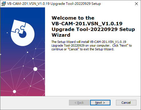
- Download and open the firmware update tool. Click Next to continue the installation process.
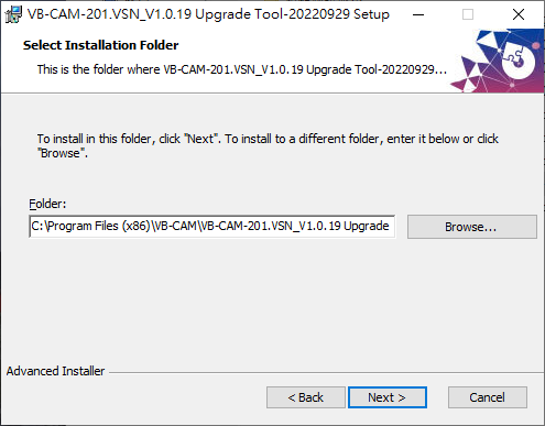
- Click Browse to select a different installation folder or click Next to continue the installation.
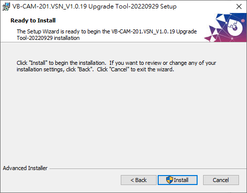
- Click Install to begin the installation.
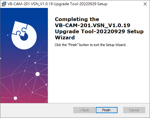
- When the installation is complete, click Finish.
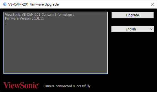
- Open the VB-CAM-201 firmware update tool.
- Connect the VB-CAM-201 to your computer via USB cable. If the VB-CAM-201 is undetected, the tool will show “Camera connection failed” and you will need to check the connection status on your computer.
- NOTE: Connect your USB cable to the USB 3.0 port. The USB 2.0 port is only designed for external microphone connection.
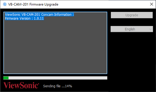
- Click Upgrade to start the firmware update process.
- NOTE: Wait for the update process to complete and do not disconnect the power or USB cable.
- Once the update is complete, the message “This is the latest Firmware version” will appear.
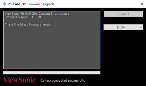
- NOTE:
- Do not disconnect or power off during the update.
- The update tool supports multiple languages.
- NOTE:


Compliance Information
This section addresses all connected requirements and statements regarding regulations. Confirmed corresponding applications shall refer to nameplate labels and relevant markings on the unit.
FCC Compliance Statement
This device complies with part 15 of FCC Rules. Operation is subject to the following two conditions: (1) this device may not cause harmful interference, and (2) this device must accept any interference received, including interference that may cause undesired operation. This equipment has been tested and found to comply with the limits for a Class B digital device, pursuant to part 15 of the FCC Rules.
These limits are designed to provide reasonable protection against harmful interference in a residential installation. This equipment generates, uses, and can radiate radio frequency energy, and if not installed and used in accordance with the instructions, may cause harmful interference to radio communications. However, there is no guarantee that interference will not occur in a particular installation. If this equipment does cause harmful interference to radio or television reception, which can be determined by turning the equipment off and on, the user is encouraged to try to correct the interference by one or more of the following measures:
- Reorient or relocate the receiving antenna.
- Increase the separation between the equipment and receiver.
- Connect the equipment into an outlet on a circuit different from that to which the receiver is connected.
- Consult the dealer or an experienced radio/TV technician for help.
Warning: You are cautioned that changes or modifications not expressly approved by the party responsible for compliance could void your authority to operate the equipment.
Industry Canada Statement
CAN ICES(B) / NMB(B)
FCC Radiation Exposure Statement
This equipment complies with FCC radiation exposure limits set forth for an uncontrolled environment. This equipment should be installed and operated with a minimum distance of 20 cm between the radiator & your body.
Validity of using the module certification: In the event that these conditions cannot be met (for example certain laptop configurations or co-location with another transmitter), then the FCC authorization for this module in combination with the host equipment is no longer considered valid and the FCC ID of the module cannot be used on the final product. In these circumstances, the OEM integrator will be responsible for re-evaluating the end product (including the transmitter) and obtaining a separate FCC authorization.
Custom design antennas may be used, however the OEM installer must following the FCC 15.21 requirements and verify if new FCC approval will be necessary.
IC Warning Statement
This device complies with Industry Canada license- exempt RSS standard(s). Operation is subject to the following two conditions: (1) this device may not cause interference, and (2) this device must accept any interference, including interference that may cause undesired operation of the device.
Le présent appareil est conforme aux CNR d’Industrie Canada applicables aux appareils radio exempts de licence. L’exploitation est autorisée aux deux conditions suivantes : ( 1 ) l’appareil ne doit pas produire de brouillage, et ( 2) l’utilisateur de l’appareil doit accepter tout brouillage radioélectrique subi, méme si le brouillage est susceptible d’en compromettre le fonctionnement.
Country Code Statement
For product available in the USA/Canada market, only channel 1~11 can be operated. Selection of other channels is not possible.
Pour les produits disponibles aux États-Unis/Canada du marché, seul le canal 1 à 11 peuvent être exploités. Sélection d’autres canaux n’est pas possible.
IC Radiation Exposure Statement
This equipment complied with IC RSS-102 radiation exposure limits set forth for an uncontrolled environment. This equipment should be installed and operated with minimum distance 20cm between the radiator & your body. The device for the band 5150-5825 MHz is only for indoor usage to reduce potential for harmful interference to co-channel mobile satellite systems.
Cet équipement est conforme aux limites d’exposition aux rayonnements IC établies pour un environnement non contrôlê. Cet équipement doit être installé et utilize avec un minimum de 20cm de distance entre la source de rayonnement et votre corps. les dispositifs fonctionnant dans la bande 5150-5825 MHz sont réservés uniquement pour une utilisation à l’intérieur afin de réduire les risques de brouillage préjudiciable aux systèmes de satellites mobiles utilisant les mêmes canaux.
CE Conformity for European Countries

The device complies with the EMC Directive 2014/30/EU and Low Voltage Directive 2014/35/EU.
The following information is only for EU-member states:
The mark shown to the right is in compliance with the Waste Electrical and Electronic Equipment Directive 2012/19/EU (WEEE). The mark indicates the requirement NOT to dispose of the equipment as unsorted municipal waste, but use the return and collection systems according to local law.
Declaration of RoHS2 Compliance
This product has been designed and manufactured in compliance with Directive 2011/65/EU of the European Parliament and the Council on restriction of the use of certain hazardous substances in electrical and electronic equipment (RoHS2 Directive) and is deemed to comply with the maximum concentration values issued by the European Technical Adaptation Committee (TAC) as shown below.
| Substance | Proposed Maximum Concentration | Actual Concentration |
|---|---|---|
| Lead (Pb) | 0.1% | < 0.1% |
| Mercury (Hg) | 0.1% | < 0.1% |
| Cadmium (Cd) | 0.01% | < 0.01% |
| Hexavalent Chromium (Cr6⁺) | 0.1% | < 0.1% |
| Polybrominated biphenyls (PBB) | 0.1% | < 0.1% |
| Polybrominated diphenyl ethers (PBDE) | 0.1% | < 0.1% |
| Bis (2-ethylhexyl) phthalate (DEHP) | 0.1% | < 0.1% |
| Butyl benzyl phthalate (BBP) | 0.1% | < 0.1% |
| Dibutyl phthalate (DBP) | 0.1% | < 0.1% |
| Diisobutyl phthalate (DIBP) | 0.1% | < 0.1% |
Certain components of products as stated above are exempted under the Annex III of the RoHS2 Directives as noted below. Examples of exempted components are:
- Copper alloy containing up to 4% lead by weight.
- Lead in high melting temperature type solders (i.e. lead-based alloys containing 85% by weight or more lead).
- Electrical and electronic components containing lead in a glass or ceramic other than dielectric ceramic in capacitors, e.g. piezoelectronic devices, or in a glass or ceramic matrix compound.
- Lead in dielectric ceramic in capacitors for a rated voltage of 125 V AC or 250 V DC or higher.
Indian Restriction of Hazardous Substances
Restriction on Hazardous Substances statement (India). This product complies with the “India E-waste Rule 2011” and prohibits use of lead, mercury, hexavalent chromium, polybrominated biphenyls or polybrominated diphenyl ethers in concentrations exceeding 0.1 weight % and 0.01 weight % for cadmium, except for the exemptions set in Schedule 2 of the Rule.
Product Disposal at End of Product Life
ViewSonic® respects the environment and is committed to working and living green. Thank you for being part of Smarter, Greener Computing. Please visit the ViewSonic® website to learn more.
USA & Canada:
https://www.viewsonic.com/us/go-green-with-viewsonic
Europe:
https://www.viewsonic.com/eu/environmental-social-governance/recycle
Taiwan:
https://recycle.moenv.gov.tw/
For EU users, please contact us for any safety/accident issue experienced with this product:
| ViewSonic Europe Limited Flevolaan 38, 1382JZ, Weesp the Netherlands | |
| +31 08000232999 | |
| EPREL@viewsoniceurope.com | |
| https://www.viewsonic.com/eu/ |
Copyright Information
Copyright© ViewSonic® Corporation, 2023. All rights reserved.
Macintosh and Power Macintosh are registered trademarks of Apple Inc.
Microsoft, Windows, and the Windows logo are registered trademarks of Microsoft Corporation in the United States and other countries.
ViewSonic®, the three birds logo, OnView, ViewMatch, and ViewMeter are registered trademarks of ViewSonic® Corporation.
VESA is a registered trademark of the Video Electronics Standards Association. DPMS, DisplayPort, and DDC are trademarks of VESA.
ENERGY STAR® is a registered trademark of the U.S. Environmental Protection Agency (EPA).
As an ENERGY STAR® partner, ViewSonic® Corporation has determined that this product meets the ENERGY STAR® guidelines for energy efficiency.
Disclaimer: ViewSonic® Corporation shall not be liable for technical or editorial errors or omissions contained herein; nor for incidental or consequential damages resulting from furnishing this material, or the performance or use of this product.
In the interest of continuing product improvement, ViewSonic® Corporation reserves the right to change product specifications without notice. Information in this document may change without notice.
No part of this document may be copied, reproduced, or transmitted by any means, for any purpose without prior written permission from ViewSonic® Corporation.
VB-CAM-201_UG_ENG_1f_20230703
For technical support or product service, see the table below or contact your reseller.
Americas
| Country/Region | Website |
|---|---|
| Canada | https://www.viewsonic.com/us |
| Latin America | https://www.viewsonic.com/la |
| United States | https://www.viewsonic.com/us |
Asia Pacific & Africa
| Country/Region | Website |
|---|---|
| Australia | https://viewsonic.com/au/ |
| Bangladesh | https://www.viewsonic.com/bd/ |
| 中国 (China) | https://www.viewsonic.com.cn |
| 香港 (繁體中文) | https://www.viewsonic.com/hk/ |
| Hong Kong (English) | https://www.viewsonic.com/hk-en/ |
| India | https://www.viewsonic.com/in/ |
| Indonesia | https://www.viewsonic.com/id/ |
| Israel | https://www.viewsonic.com/il/ |
| 日本 (Japan) | https://www.viewsonic.com/jp/ |
| Korea | https://www.viewsonic.com/kr/ |
| Malaysia | https://www.viewsonic.com/my/ |
| Middle East | https://www.viewsonic.com/me/ |
| Myanmar | https://www.viewsonic.com/mm/ |
| Nepal | https://www.viewsonic.com/np/ |
| New Zealand | https://www.viewsonic.com/nz/ |
| Pakistan | https://www.viewsonic.com/pk/ |
| Philippines | https://www.viewsonic.com/ph/ |
| Singapore | https://www.viewsonic.com/sg/ |
| 臺灣 (Taiwan) | https://www.viewsonic.com/tw/ |
| ประเทศไทย | https://www.viewsonic.com/th/ |
| Việt Nam | https://www.viewsonic.com/vn/ |
| South Africa & Mauritius | https://www.viewsonic.com/za/ |
Europe
| Country/Region | Website |
|---|---|
| Europe | https://www.viewsonic.com/eu/ |
| France | https://www.viewsonic.com/fr/ |
| Deutschland | https://www.viewsonic.com/de/ |
| Қазақстан | https://www.viewsonic.com/kz/ |
| Россия | https://www.viewsonic.com/ru/ |
| España | https://www.viewsonic.com/es/ |
| Türkiye | https://www.viewsonic.com/tr/ |
| Україна | https://www.viewsonic.com/ua/ |
| United Kingdom | https://www.viewsonic.com/uk/ |
Limited Warranty
ViewSonic® Display
What the warranty covers:
ViewSonic® warrants its products to be free from defects in material and workmanship during the warranty period. If a product proves to be defective in material or workmanship during the warranty period, ViewSonic® will, at its sole option, and as your sole remedy, repair or replace the product with a similar product. Replacement Product or parts may include remanufactured or refurbished parts or components. The repair or replacement unit or parts or components will be covered by the balance of the time remaining on the customer’s original limited warranty and the warranty period will not be extended. ViewSonic® provides no warranty for any third-party software whether included with the product or installed by the customer, installation of any unauthorized hardware parts or components (e.g. Projector Lamps). (Please refer to: “What the warranty excludes and does not cover” section).
How long the warranty is effective:
ViewSonic® displays are warranted for between 1 and 3 years, depending on your country of purchase, for all parts including the light source and for all labor from the date of the first consumer purchase.
Who the warranty protects:
This warranty is valid only for the first consumer purchaser.
What the warranty excludes and does not cover:
- Any product on which the serial number has been defaced, modified, or removed.
- Damage, deterioration, or malfunction resulting from:
- Accident, misuse, neglect, fire, water, lightning, or other acts of nature, unauthorized product modification, or failure to follow instructions supplied with the product.
- Repair or attempted repair by anyone not authorized by ViewSonic®.
- Damage to or loss of any programs, data, or removable storage media.
- Normal wear and tear.
- Removal or installation of the product.
- Software or data loss occurring during repair or replacement.
- Any damage of the product due to shipment.
- Causes external to the product, such as electric power fluctuations or failure.
- Use of supplies or parts not meeting ViewSonic’s specifications.
- Failure of owner to perform periodic product maintenance as stated in the User Guide.
- Any other cause which does not relate to a product defect.
- Damage caused by static (non-moving) images displayed for lengthy periods of time (also referred to as image burn-in).
- Software - Any third-party software included with the product or installed by the customer.
- Hardware/Accessories/Parts/Components – Installation of any unauthorized hardware, accessories, consumable parts or components (e.g. Projector Lamps).
- Damage to, or abuse of, the coating on the surface of the display through inappropriate cleaning as described in the product User Guide.
- Removal, installation, and set-up service charges, including wall-mounting of the product.
How to get service:
- For information about receiving service under warranty, contact ViewSonic® Customer Support (Please refer to the “Customer Service” page). You will need to provide your product’s serial number.
- To obtain warranty service, you will be required to provide: (a) the original dated sales slip, (b) your name, (c) your address, (d) a description of the problem, and (e) the serial number of the product.
- Take or ship the product, freight prepaid, in the original container to an authorized ViewSonic® service center or ViewSonic®.
- For additional information or the name of the nearest ViewSonic® service center, contact ViewSonic®.
Limitation of implied warranties:
There are no warranties, express or implied, which extend beyond the description contained herein including the implied warranty of merchantability and fitness for a particular purpose.
Exclusion of damages:
ViewSonic’s liability is limited to the cost of repair or replacement of the product. ViewSonic® shall not be liable for:
- Damage to other property caused by any defects in the product, damages based upon inconvenience, loss of use of the product, loss of time, loss of profits, loss of business opportunity, loss of goodwill, interference with business relationships, or other commercial loss, even if advised of the possibility of such damages.
- Any other damages, whether incidental, consequential or otherwise.
- Any claim against the customer by any other party.
- Repair or attempted repair by anyone not authorized by ViewSonic®.
Effect of state law:
This warranty gives you specific legal rights, and you may also have other rights which vary from state to state. Some states do not allow limitations on implied warranties and/or do not allow the exclusion of incidental or consequential damages, so the above limitations and exclusions may not apply to you.
Sales outside the U.S.A. and Canada:
For warranty information and service on ViewSonic® products sold outside of the U.S.A. and Canada, contact ViewSonic® or your local ViewSonic® dealer. The warranty period for this product in mainland China (Hong Kong, Macao, and Taiwan Excluded) is subject to the terms and conditions of the Maintenance Guarantee Card. For users in Europe and Russia, full details of warranty provided can be found at: ViewSonic EU under “Support/Warranty Information”.
Mexico Limited Warranty
ViewSonic® Display
What the warranty covers:
ViewSonic® warrants its products to be free from defects in material and workmanship, under normal use, during the warranty period. If a product proves to be defective in material or workmanship during the warranty period, ViewSonic® will, at its sole option, repair or replace the product with a like product. Replacement product or parts may include remanufactured or refurbished parts or components & accessories.
How long the warranty is effective:
ViewSonic® LCD displays are warranted for between 1 and 3 years, depending on your country of purchase, for all parts including the light source and for all labour from the date of the first consumer purchase.
Who the warranty protects:
This warranty is valid only for the first consumer purchaser.
What the warranty excludes and does not cover:
- Any product on which the serial number has been defaced, modified, or removed.
- Damage, deterioration, or malfunction resulting from:
- Accident, misuse, neglect, fire, water, lightning, or other acts of nature, unauthorized product modification, or failure to follow instructions supplied with the product.
- Causes external to the product, such as electrical power fluctuations or failure.
- Use of supplies or parts not meeting ViewSonic®’s specifications.
- Normal wear and tear.
- Removal or installation of the product.
How to get service:
- For information about receiving service under warranty, contact ViewSonic® Customer Support (Please refer to the “Customer Service” page). You will need to provide your product’s serial number, so please record the product information in the space provided below on your purchase for your future use. Please retain your receipt of proof of purchase to support your warranty claim.
- To obtain warranty service, you will be required to provide: (a) the original dated sales slip, (b) your name, (c) your address, (d) a description of the problem, and (e) the serial number of the product.
- Take or ship the product, freight prepaid, in the original container to an authorized ViewSonic® service center.
- Round trip transportation costs for in-warranty products will be paid by ViewSonic®.
Limitation of implied warranties:
There are no warranties, express or implied, which extend beyond the description contained herein including the implied warranty of merchantability and fitness for a particular purpose.
Exclusion of damages:
ViewSonic®’s liability is limited to the cost of repair or replacement of the product. ViewSonic® shall not be liable for:
- Damage to other property caused by any defects in the product, damages based upon inconvenience, loss of use of the product, loss of time, loss of profits, loss of business opportunity, loss of goodwill, interference with business relationships, or other commercial loss, even if advised of the possibility of such damages.
- Any other damages, whether incidental, consequential or otherwise.
- Any claim against the customer by any other party.
- Repair or attempted repair by anyone not authorized by ViewSonic®.
| Contact Information for Sales & Authorized Service (Centro Autorizado de Servicio) within Mexico: | |
|---|---|
|
Name, address, of manufacturer and importers:
| |
| NÚMERO GRATIS DE ASISTENCIA TÉCNICA PARA TODO MÉXICO: 001.866.823.2004 | |
|
Hermosillo:
|
Villahermosa:
|
|
Puebla, Pue. (Matriz):
|
Veracruz, Ver.:
|
|
Chihuahua:
|
Cuernavaca:
|
|
Distrito Federal:
|
Guadalajara, Jal.:
|
|
Guerrero Acapulco:
|
Monterrey:
|
|
MERIDA:
|
Oaxaca, Oax.:
|
|
Tijuana:
|
FOR USA SUPPORT:
|