MPC310-W31-TU
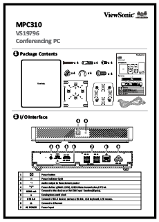
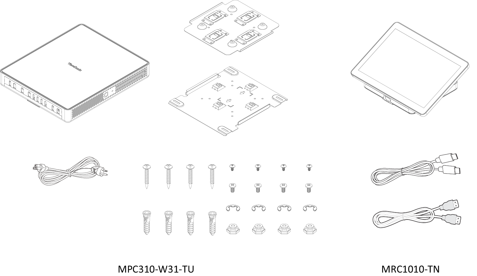
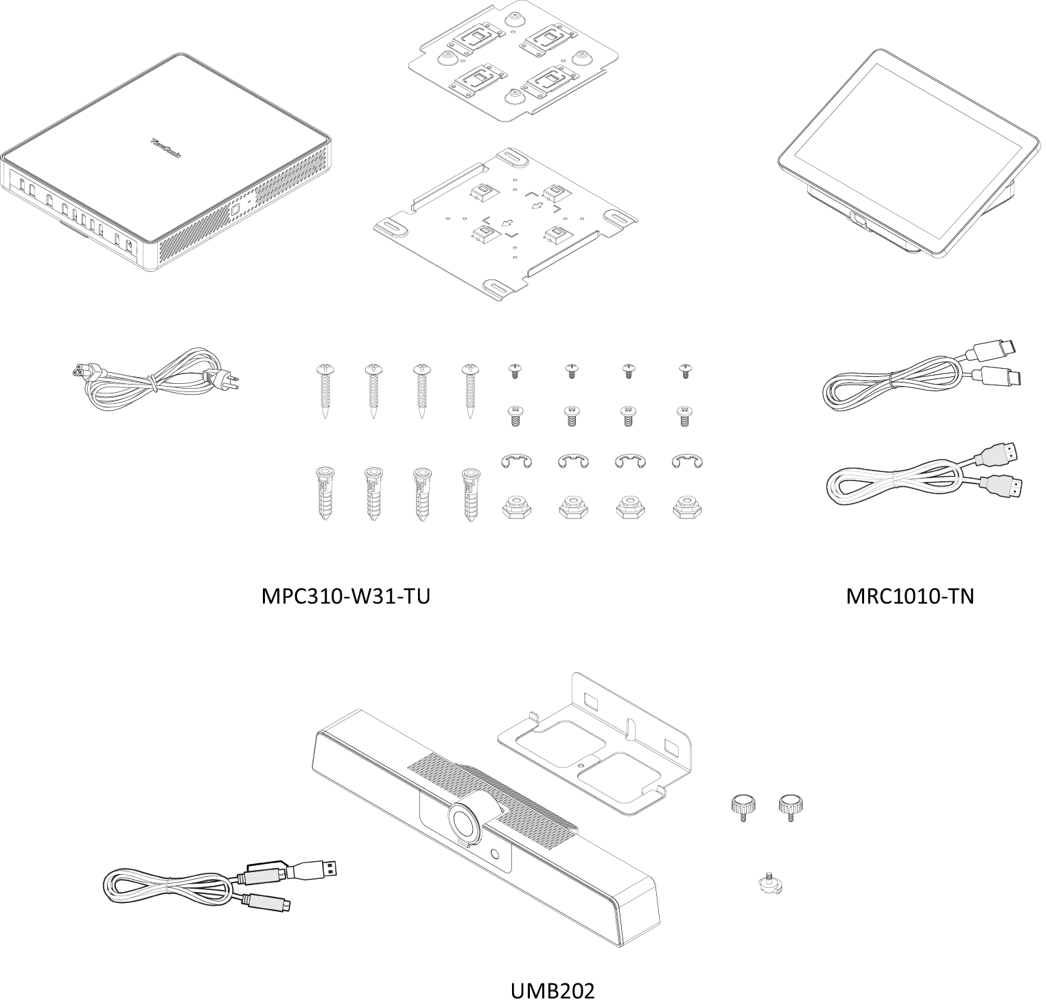
Package Contents
- Note: If anything is missing or damaged, please contact your local reseller for more information
MPC310-W31-TU
| Item | Description | |
|---|---|---|
| 1 | Power Button. | |
| 2 | Power indicator light. | |
| 3 | Audio output to an external audio device. | |
| 4 |
| |
| 5 | HDMI OUT | Connection port for displays with HDMI input support. |
| 6 | Security lock. | |
| 7 | USB 3.0 | Connection for USB peripherial device(s) (e.g., storage device, keyboard, mouse, etc.). |
| 8 | Ethernet connection. | |
| 9 | AC POWER | Power input socket. |
Installing the Conference PC
With the included VESA Mounting Bracket set, the Conferencing PC can be attached to a wall, table, or trolley.
Installing the VESA Mounting Bracket (PC Side) onto the Conferencing PC
Attach the VESA Mounting Bracket (PC Side) to the Conferencing PC with four Bracket Screws (M3 x 6 mm).
Installing the VESA Mounting Bracket (Wall/Table/Trolley Side) and Conferencing PC
Wall Mounting
- Pre-drill four holes into the wall and install four Anchors (Ø6.0 x 25 mm).
- Align the VESA Mounting Bracket (Wall/Table/Trolley Side) with the four Anchors, then secure the VESA Mounting Bracket with four Anchor Screws (T4 x 20 mm).
- Attach the Conferencing PC to the VESA Mounting Bracket.
Table Mounting
- Pre-drill four holes into the table and install four Anchors (Ø6.0 x 25 mm).
- Align the VESA Mounting Bracket (Wall/Table/Trolley Side) with the four Anchors, then secure the VESA Mounting Bracket with four Anchor Screws (T4 x 20 mm).
- Attach the Conferencing PC to the VESA Mounting Bracket.
Trolley Mounting
- Select the installation location on the trolley and make sure the space is appropriate for the Conferencing PC.
- Install four Hex Nuts into the oval holes of the trolley.
- Secure the Hex Nuts with four E-type Circlips (Ø8 ).
- Align the VESA Mounting Bracket (Wall/Table/Trolley Side) with the four Hex Nuts, then secure the VESA Mounting Bracket with four Screws (M4 x 6 mm).
- Attach the Conferencing PC to the VESA Mounting Bracket.
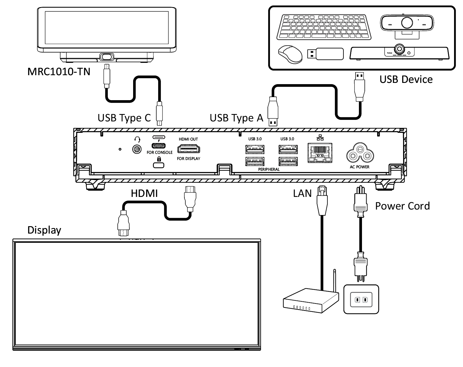
Connecting to the Touch Console
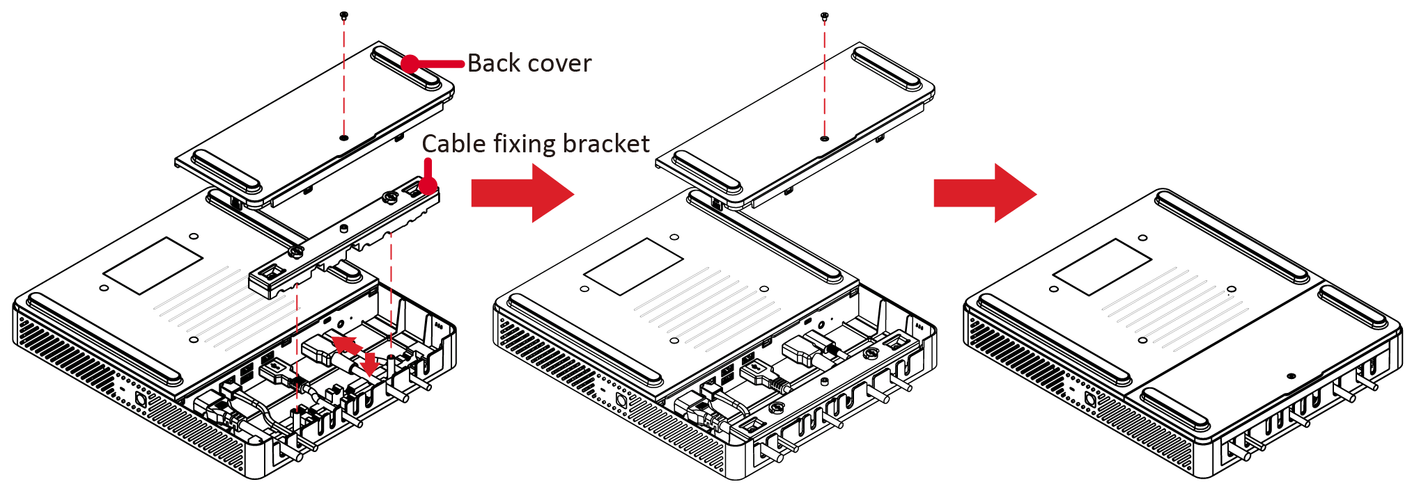
Cable Management
- Remove the back cover of the Conferencing PC and cable fixing bracket by removing the screws.
- Connect any necessary cables to the I/O ports of the Conferencing PC and direct the cables through the cable channels.
- Replace the cable fixing bracket and back cover of the Conferencing PC with the previously removed screws.
Prerequisites
Required License for Microsoft Teams Rooms (MTR)
You will need a Microsoft Teams Rooms license to set up your MTR Room System. To learn more about the required licenses, refer to the Microsoft Teams documentation: "Microsoft Teams Rooms licenses"
Required Resource Account for Microsoft Teams Rooms
To set up your Microsoft Teams Rooms system, you will also need a Microsoft Teams Rooms account. For information on setting up this account, refer to the Microsoft Teams documentation: "Create and configure resource accounts for rooms and shared Teams device"
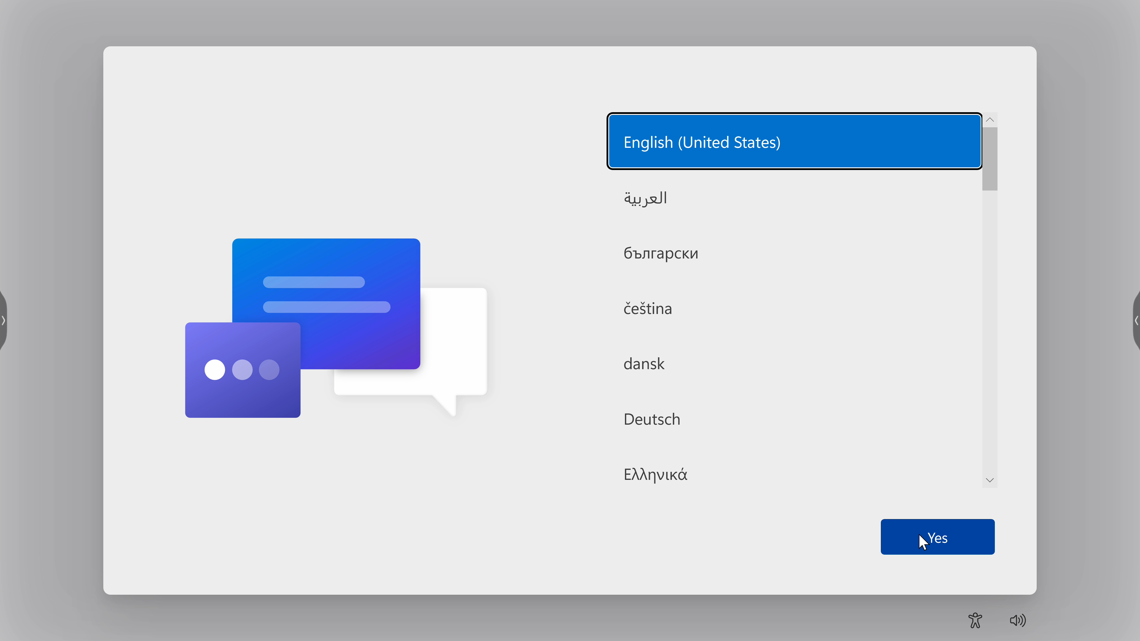
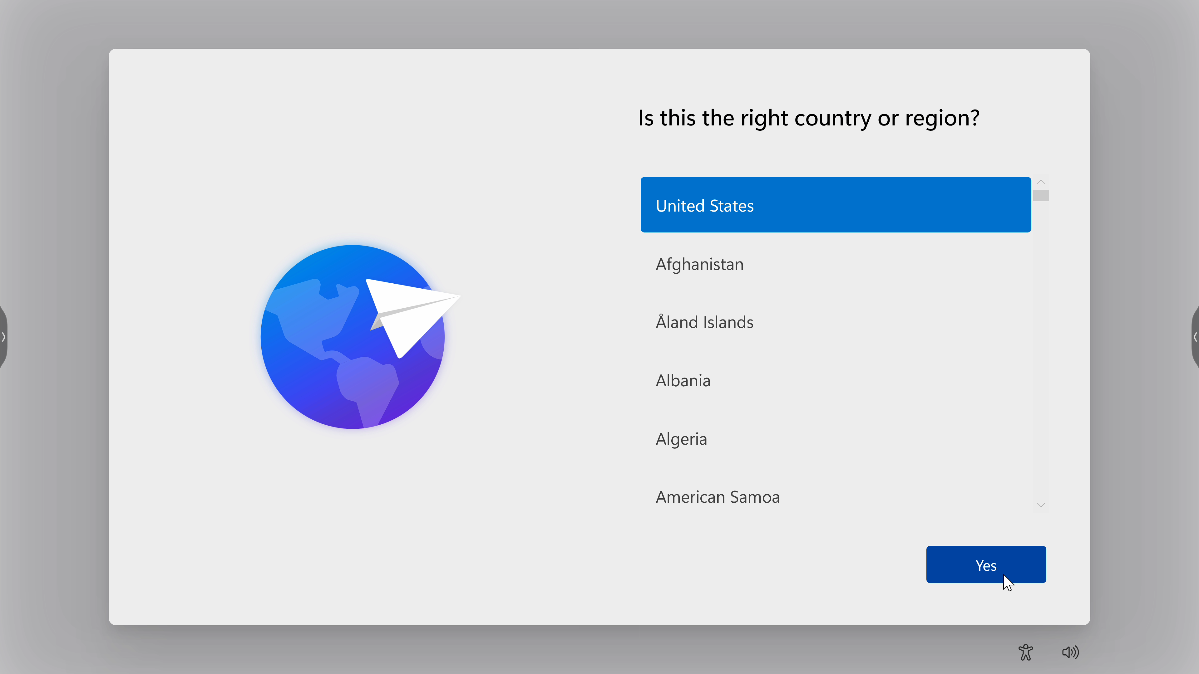
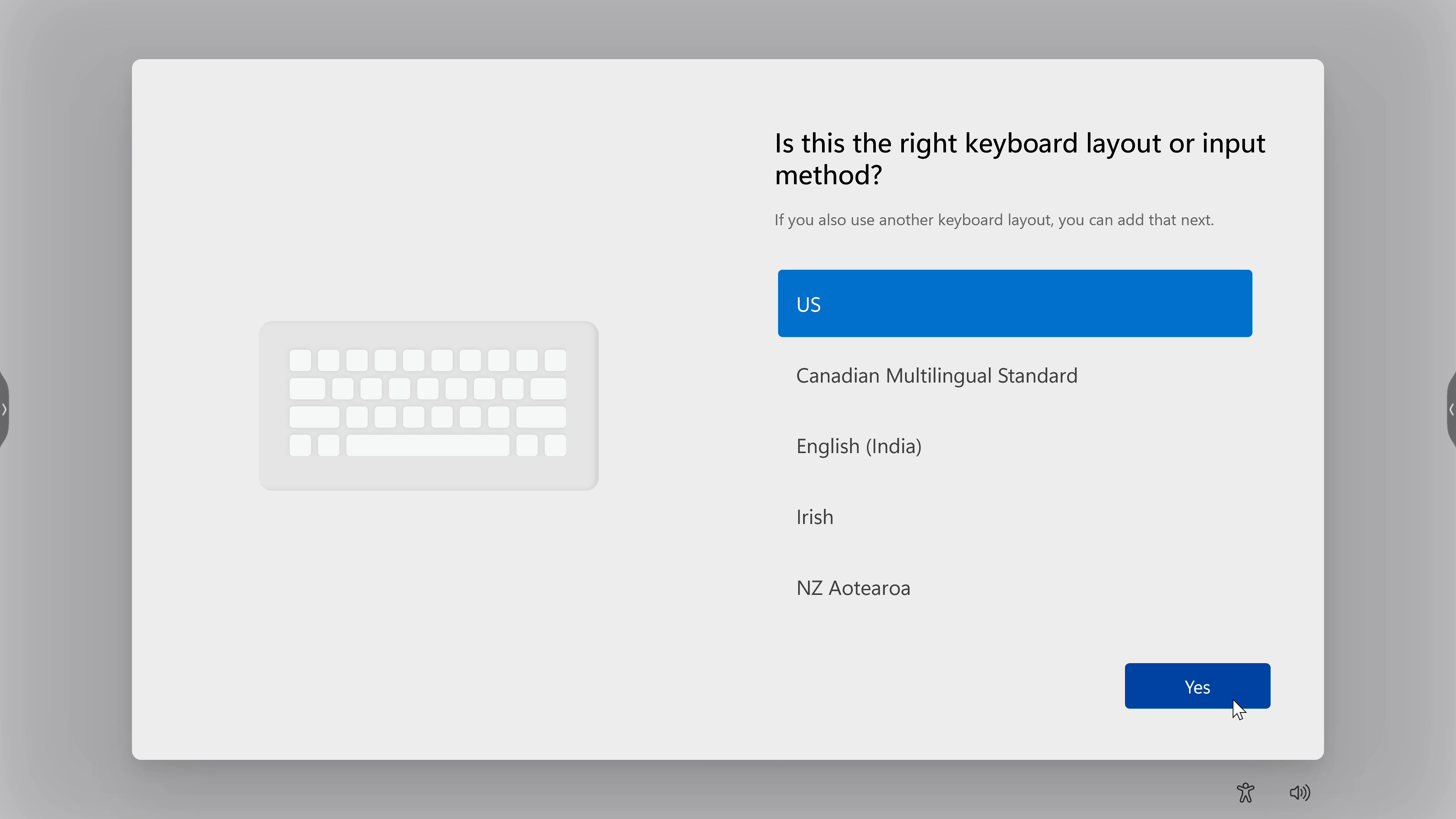
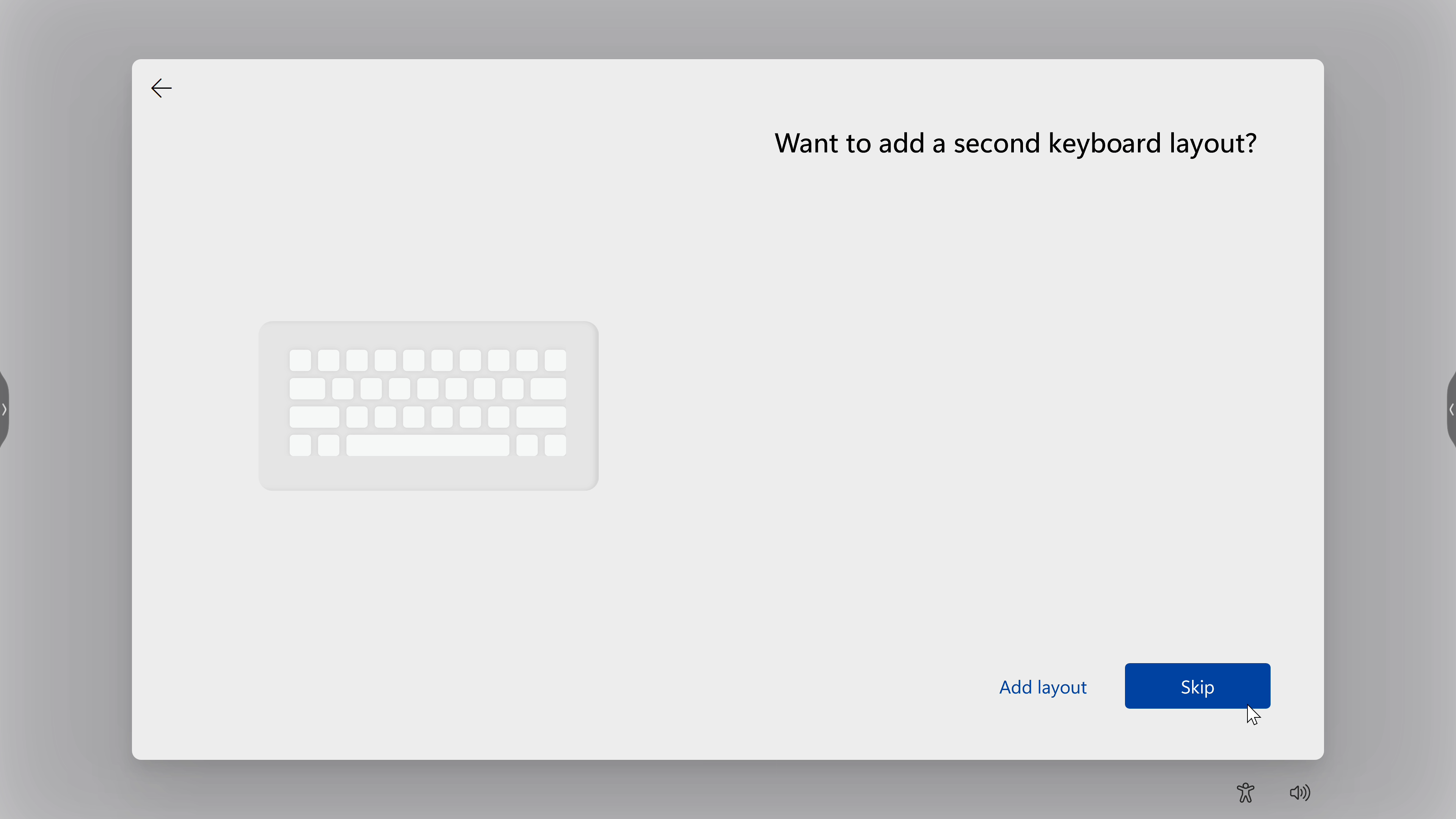
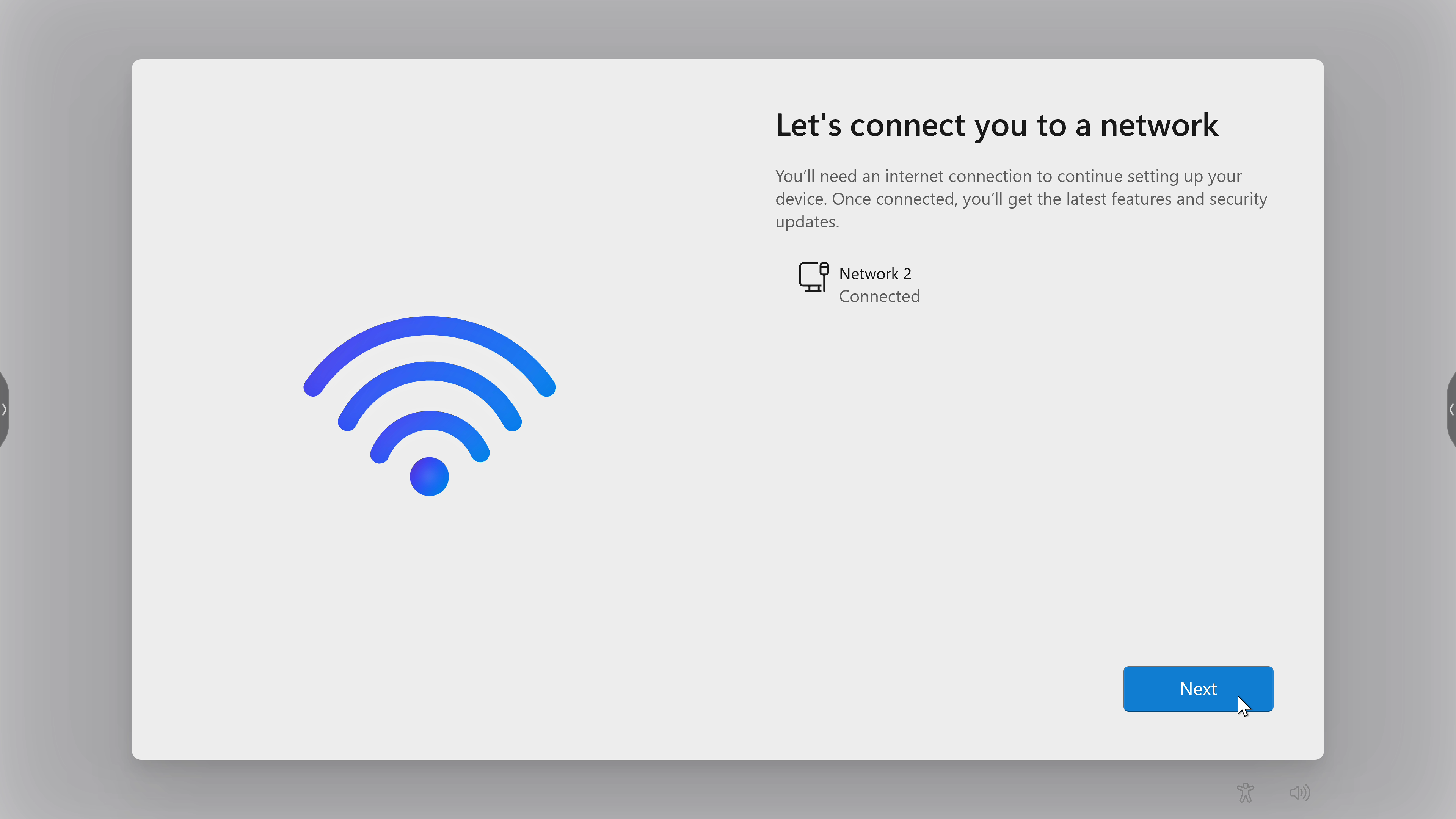
MTR Setup Wizard
-
Select language.
-
Select country or region.
-
Select keyboard layout.
-
Add a second keyboard layout.
-
Connect to a network.
-
Check for any updates and finish setting up.
MTR Account Setup
-
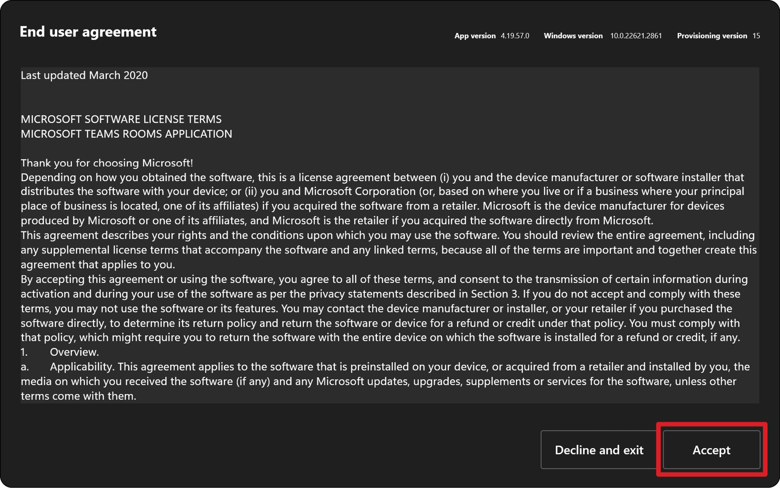
To setup a Microsoft Teams Rooms account, review the End user agreement and select Accept.
-
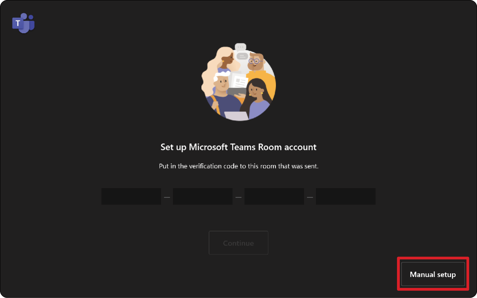
Select Manual setup.
-
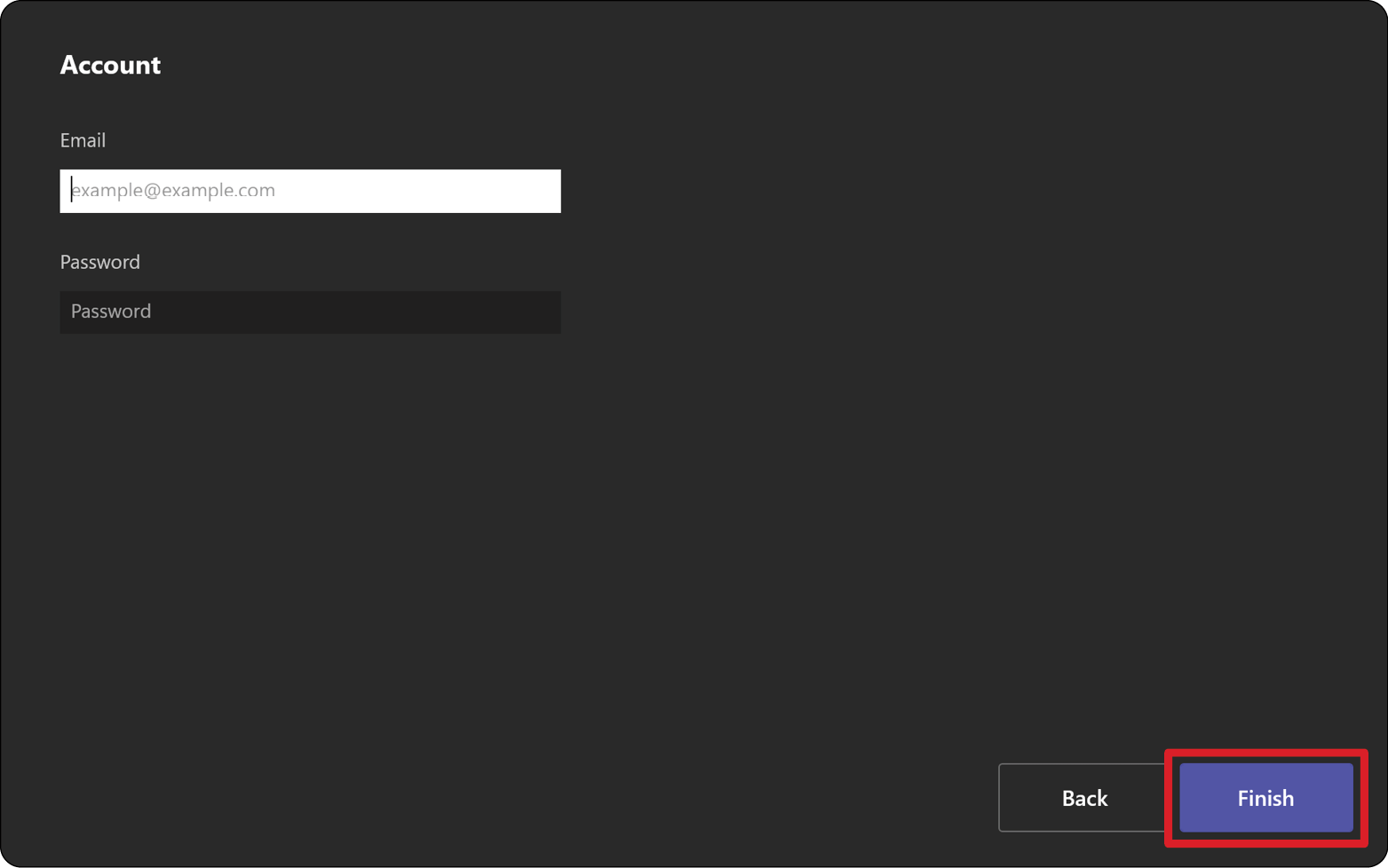
Enter the account email and password, then select Finish.
Touch Console
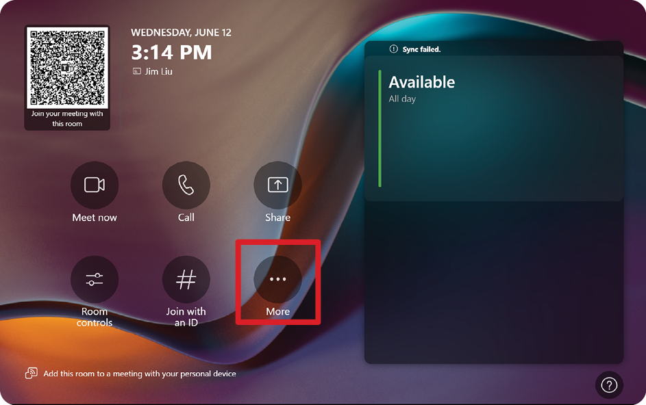
Home Screen
| Icon | Function | Description |
|---|---|---|
| Meet Now | Start a new meeting. | |
| Call | Make a phone call. | |
| Share | Project your laptop by plugging in the cable connected to the console. Depending on the room settings, it may be projected to the room automatically, or you may have to select Share on the Touch Console. You can also cast content onto the room display from your desktop or mobile device. | |
| Join with an ID | Join a meeting that is not on the calendar. | |
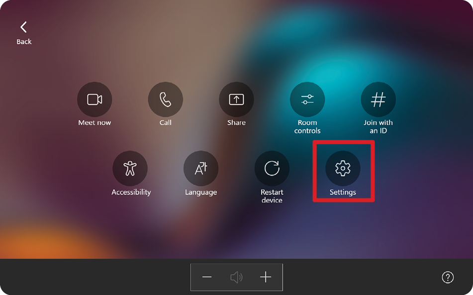
| More | View more options like adding a room, setting adjustment, etc. | |
| Accessibility | See accessibility options. | |
| Restart Device | Restart the Touch Console. | |
| Settings | Change the Touch Console settings. | |
| Room Controls | Switch to an OEM-provided application for in-room media or room lighting and/or blind controls. This option is available when configured by your administration. |
- NOTE:For more information on features see Microsoft Teams Rooms (Windows) and Get Started with Chat in Microsoft Teams.
PIR Sensor Setup
-
On the Touch Console, select More and then Settings.
-
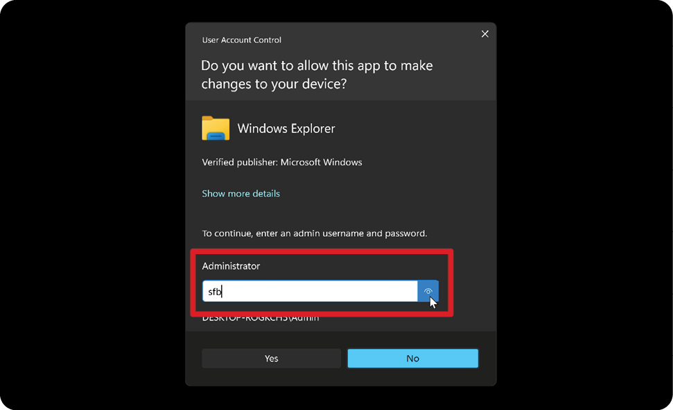
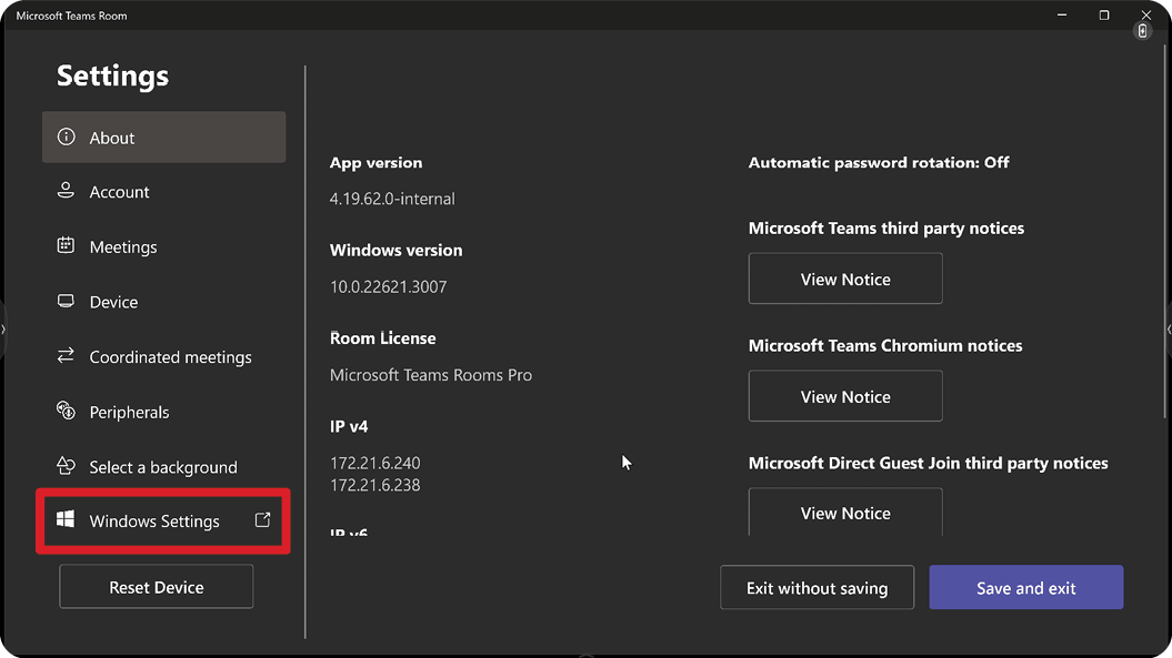
Enter the Administrator password “sfb” and select Windows Settings and Go to Admin Sign-in.
-
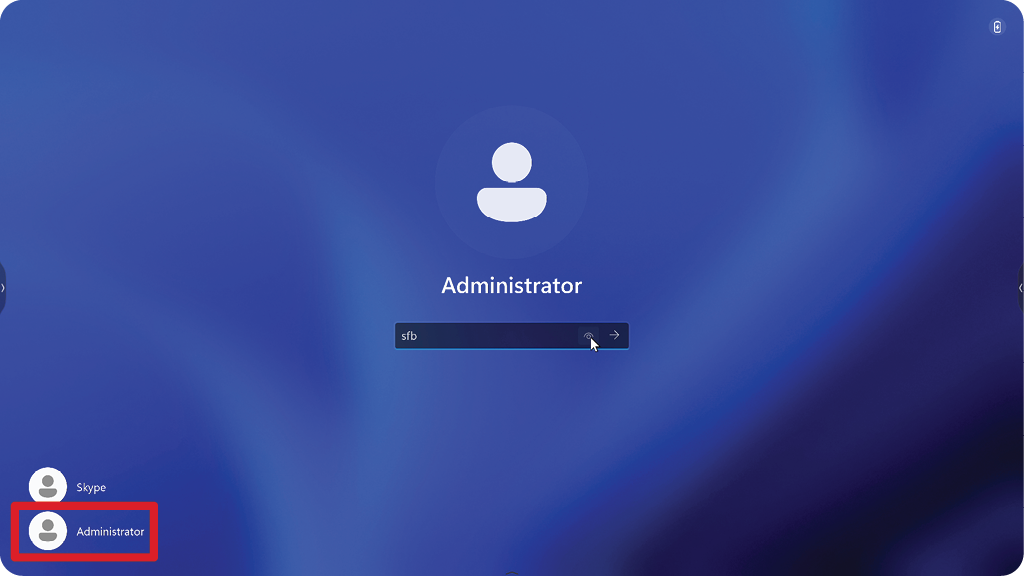
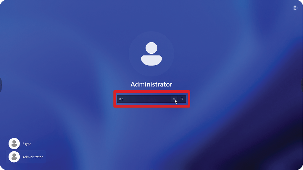
The MTR computer will log out of MTR and the Windows 11 login screen will be presented. Select the Administrator account and enter the password “sfb”.
-
In the Search Box on the Windows Task Bar, search for and open Device Manager.
-
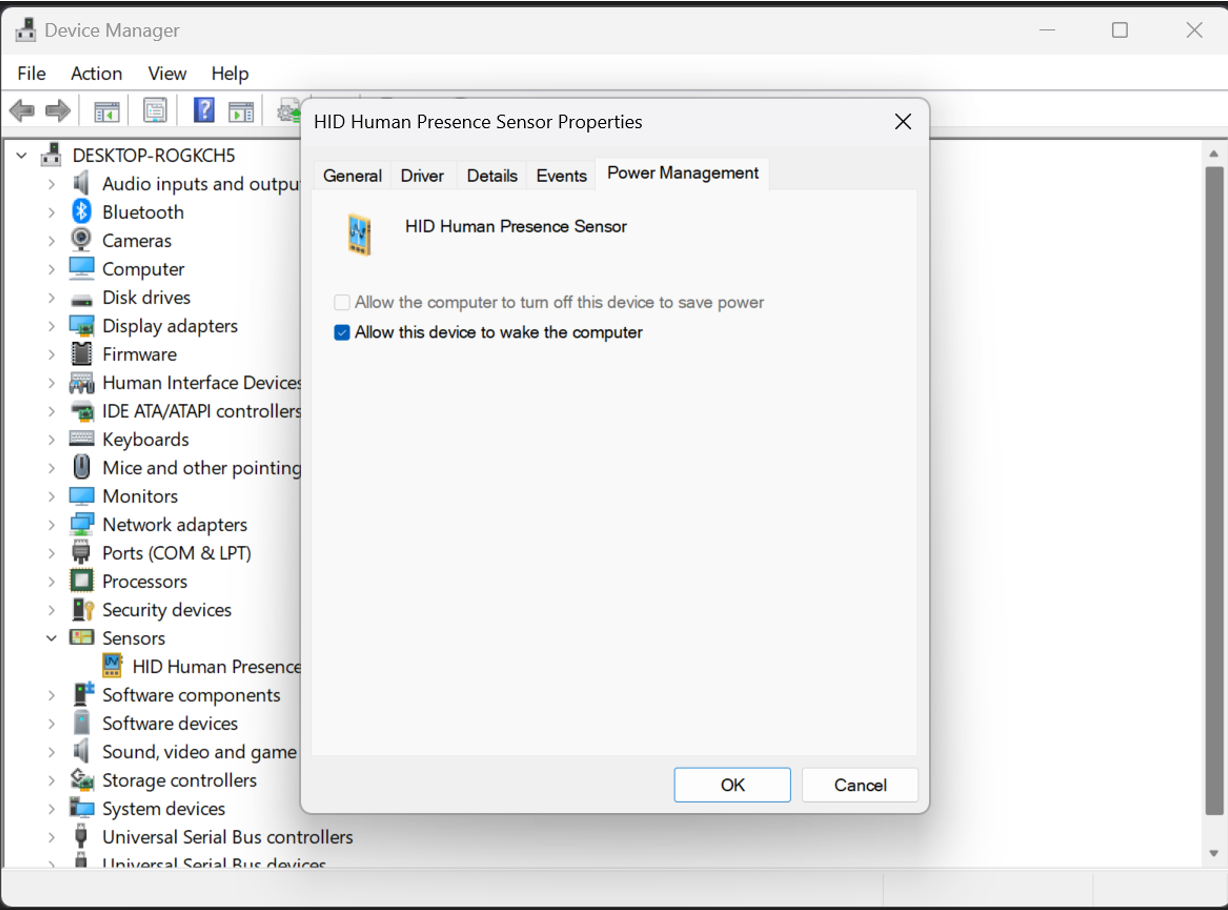
In Device Manager, select: Sensors > HID Human Presence Sensor Properties > Power Management.
-
Select the checkbox next to Allow this device to wake the computer.
"Wake on Active IFP Display" Settings
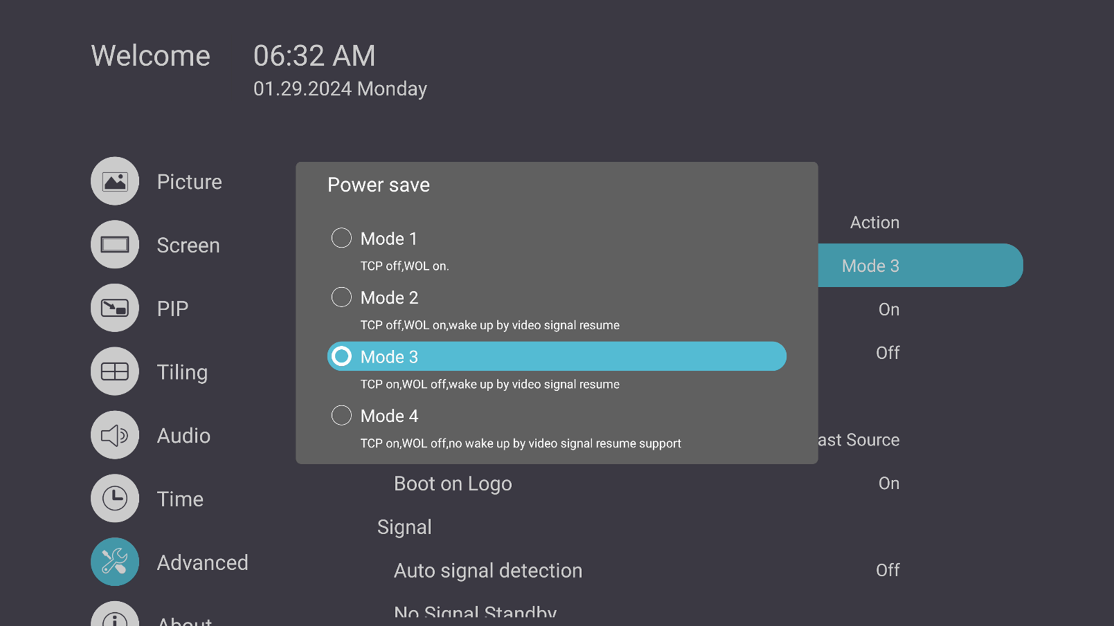
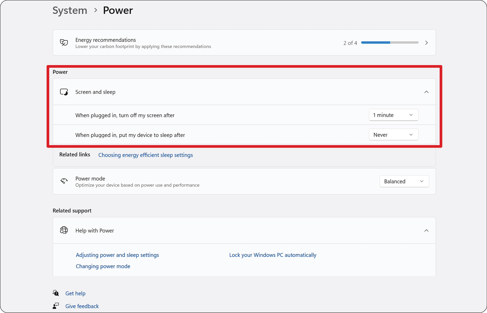
Please follow the guidelines below to wake up the IFP display from standby mode to active mode when the MTR PIR sensor makes a detection:
- Before adjusting the IFP display settings, make sure the PIR Sensor Setup is complete as this allows the device to wake the computer.
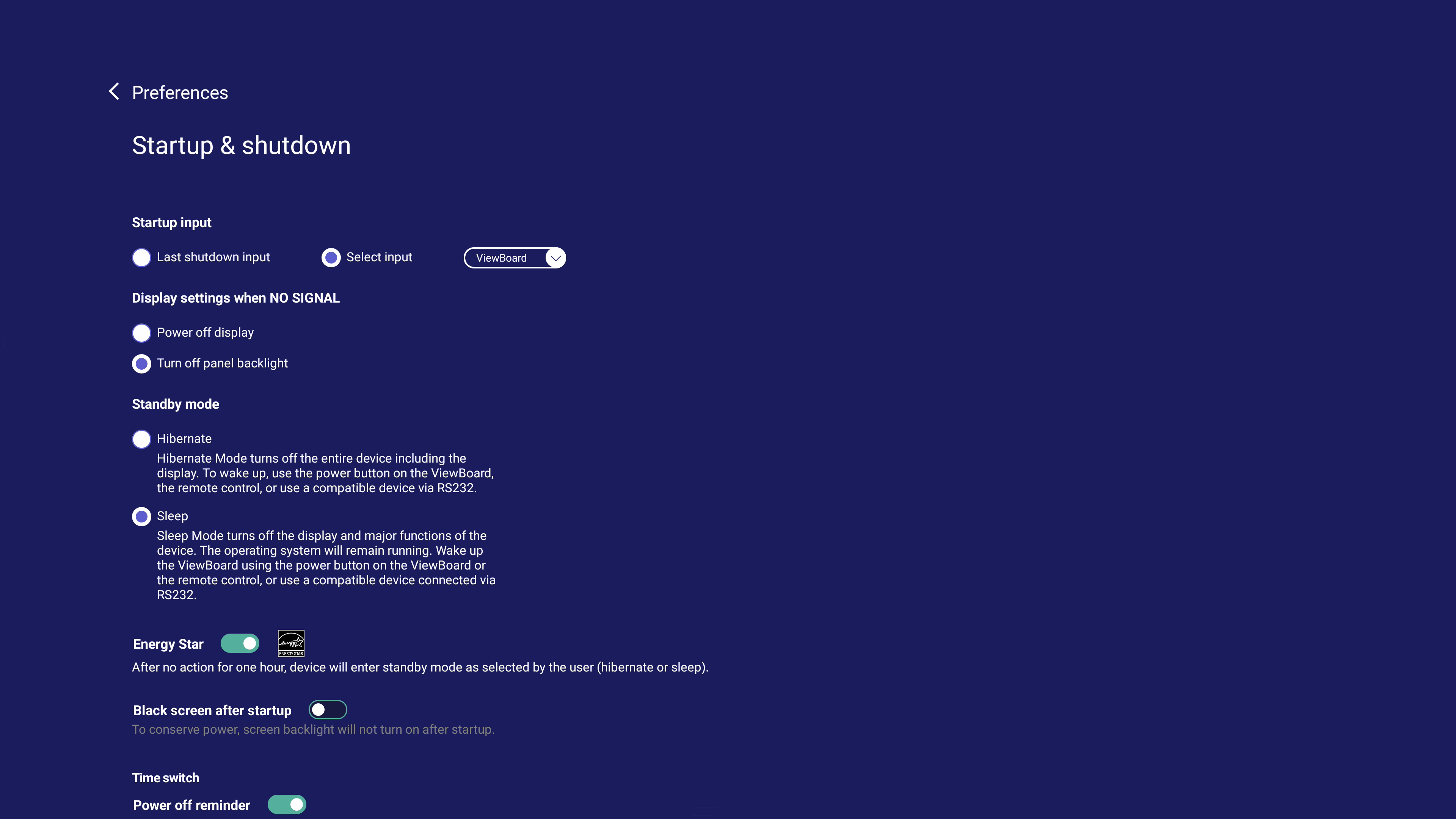
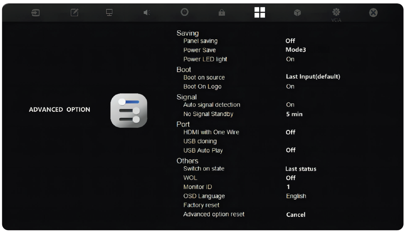
- Refer to the following examples of Startup & Shutdown/Power Save settings of the IFP /CDE series.
IFP33 Series - IFP62 Series - IFP105
CDE30 Series
IFPG1 Series
Power Save: Mode3 TCP on, WOL off, wake up by video signal resume.
Calibrate the Display for Pen or Touch
- Note: Before starting, make sure a keyboard is connected to the Conference PC.
-
On the Touch Console, select More and then Settings.
-
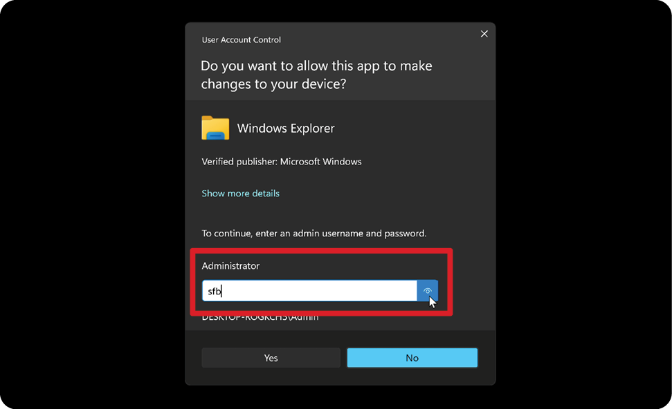
Enter the Administrator password “sfb” and select Windows Settings and Go to Admin Sign-in.
-
The MTR computer will log out of MTR and the Windows 11 login screen will be presented. Select the Administrator account and enter the password “sfb".
-
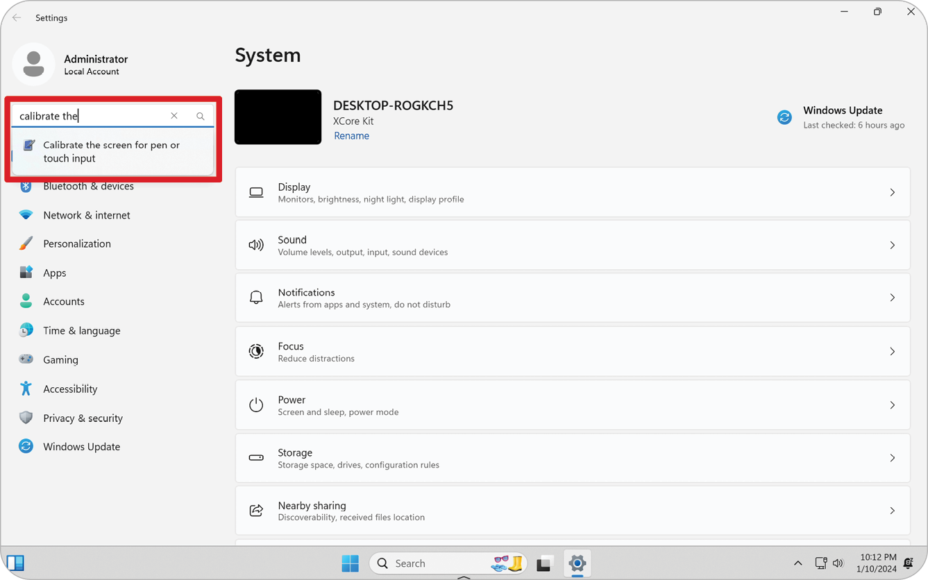
In the Search Box on the Windows Task Bar, search for and open “Calibrate the screen for pen or touch input”.
-
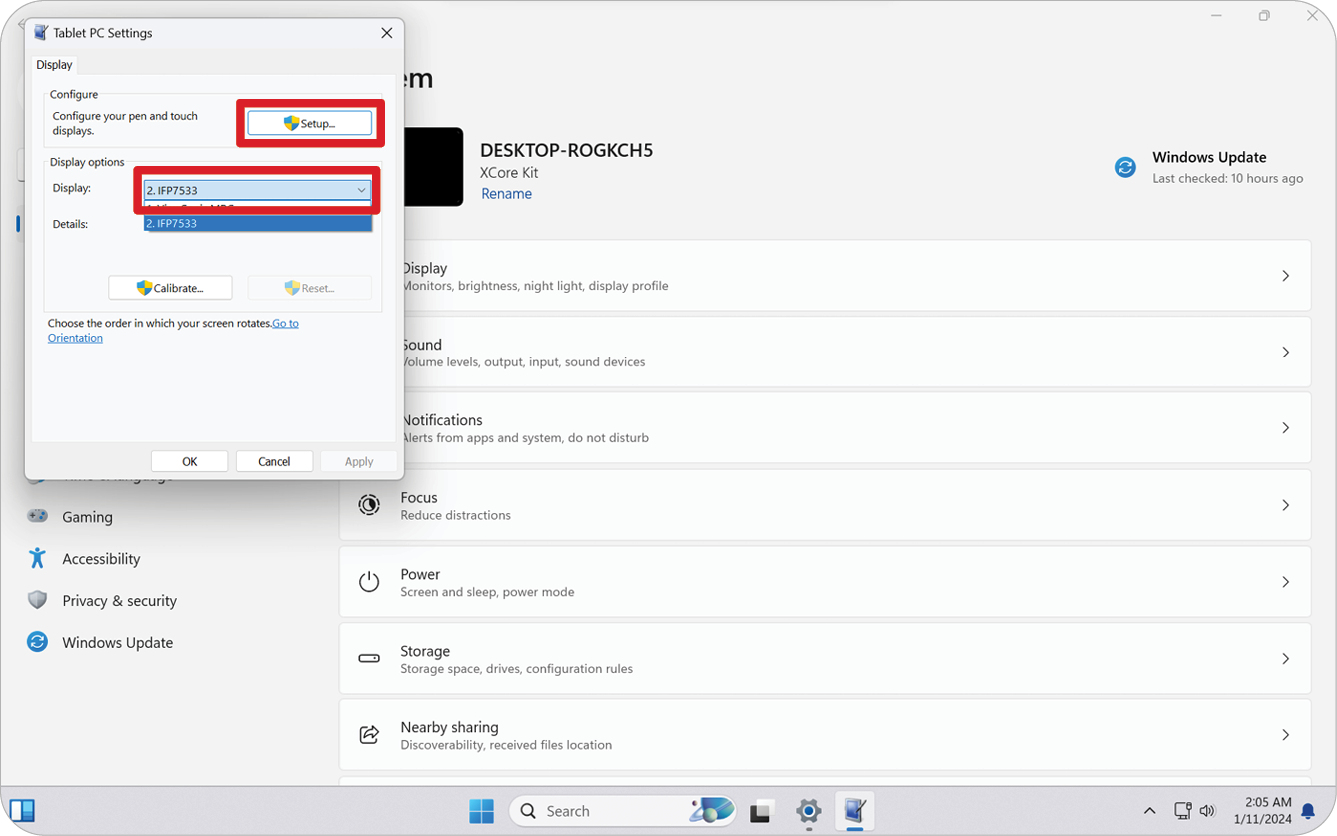
In Tablet PC Settings under Display Options select the connected display. Then, under Configure, click Setup and select Touch Input in the pop-up window.
-
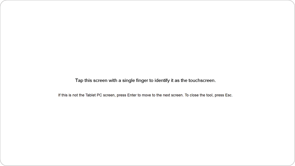
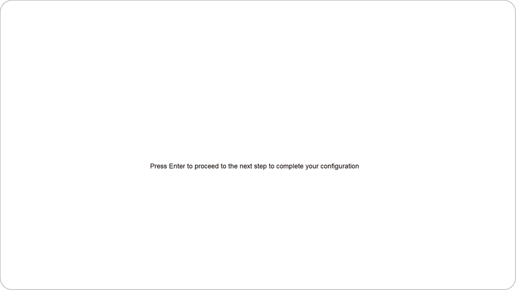
A message will appear on each display’s screen (e.g., IFP display and MRC1010-TN) one at a time instructing you to tap the screen with a single finger to identify it as the touchscreen. Tap the screen displaying this message with your finger as instructed, and press Enter on the connected keyboard to proceed.
- Note: This step will first set up the IFP display side and then set up the MRC1010-TN side, refer to the same setting screen as below
-
Repeat this for all interactive displays, including the IFP display and the MRC1010-TN Touch console.
- Note: If any non-interactive displays are being used, press Enter on the connected keyboard to skip.
SKU Overview
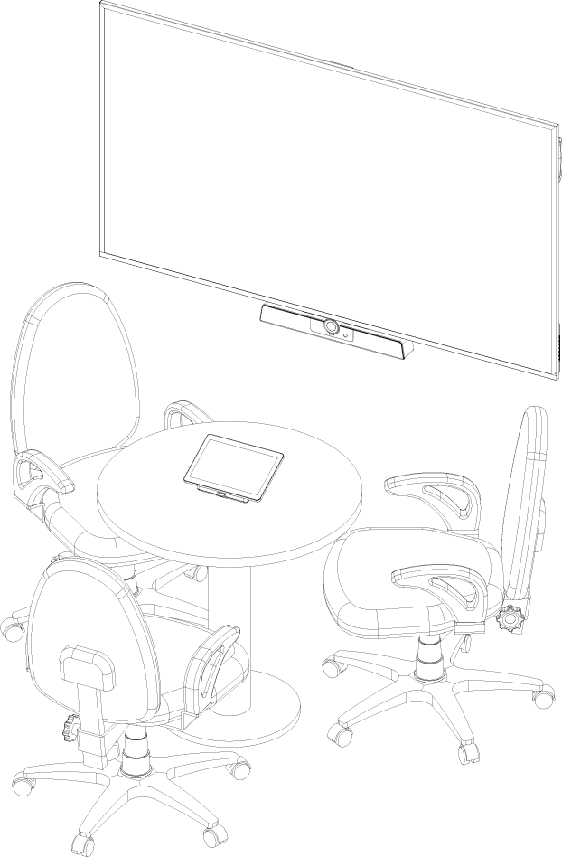
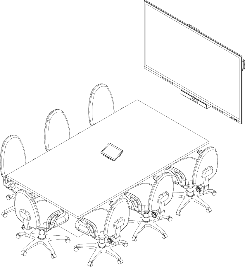
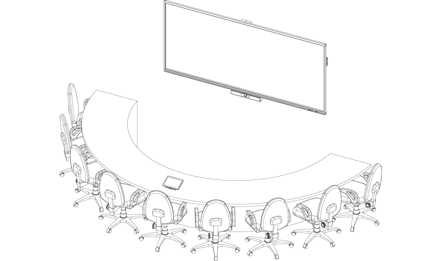
Conference Room Type
- CDE30_Series
- MPC310-W31-TU
- MRC1010-TN
- UMB202
- IFP62_Series
- MPC310-W31-TU
- MRC1010-TN
- UMB202
- 21:9 UltraWide series
- MPC310-W31-TU
- MRC1010-TN
- UMB202
Technical Specifications
| Item | Category | Specifications |
|---|---|---|
| Core | CPU | Intel® Core™ i3-1220P 1.5 GHz
Turbo boost 4.4 GHz |
| Graphic | Chipset | Integrated Intel® UHD Graphics Total Available Graphics Memory: 32 GB Max Resolution: up to 3840 x 2160 @ 30 Hz (DP) |
| Memory | Slot Type Size | 260-pin DDR4 SO-DIMM x 2 (8 GB) |
| Memory | 4GB: Major Brand Kingston, DDR4 4GB CBD32D4S2S1KC-4 3200M | |
| I/O | Ports | 4 x USB 3.0 Type A |
| 1 x USB Type C (DP Out, 4K @ 30 Hz; USB 3.0, USB 2.0; 20V/1A PD) | ||
| 1 x RJ45 (10 M/100 M/1000 M) | ||
| 1 x Audio Combo Jack | ||
| 1 x HDMI Out (supports multiple displays; CEC control - screen power on/off)
Maximum output resolution: 16:9: 3840 x 2160 @ 60 Hz 21:9: 3440 x 1440 @ 30 Hz | ||
| Acoustic | System Acoustic | ≤ 35 db |
| Compatibility | Picture
(Paint) |
JPG, JPEG, JPE, JFIF, BMP, DIB, PNG, GIF, TIF, TIFF |
| Video
(Windows Media Player) |
ASF, WMA, WMV, WM, ASX, WAX, WVX, WMX, WPL, WMD, AVI, MPG, MPEG, M1V, MP2, MP3, MPA, MPE, M3U | |
| Audio
(Windows Media Player) |
MID, MIDI, RMI, AIF, AIFC, AIFF, WAV, CDA | |
| Software | Bundled Software | Microsoft Teams Rooms |
| Physical | Dimensions | 275.5 x 230 x 43 mm
(10.85” x 9.06” x 1.69” ) |
| Weight | 1.86 kg
(4.10 lbs) | |
| Operating Conditions | Altitude | 0~3,048 m
(10,000 ft) |
| Relative Humidity | 10%~90% (non-condensing) | |
| Temperature | -10°C~40°C
(14°F~104°F) | |
| Storage Conditions | Altitude | 0~12,192 m
(40,000 ft) |
| Relative Humidity | 10%~90% (non-condensing) | |
| Temperature | -20°C~60°C
(-4°F~140°F) | |
| Power | Input Voltage | AC 100-240V, 1.5A, 50/60Hz |
| Rating Consumption | Min 15.6W (start device)
Max 90W (full loading) | |
| Standby Consumption | 1.5W | |
| Antenna | Antenna Type | Dipole |
| Manufacturer | Guangzhou ShiHan | |
| Model Name | 004.032.0052699 | |
| Antenna Gain | 3.28 dbi | |
| EIRP Max Power | 8.79 mW (module with antenna) | |
| Connector Type I | I-PEX |
Troubleshooting
| Problem or Issue | Possible Solutions |
|---|---|
| The Teams rooms solution(MPC310-W31-TU/ MRC1010-TN) won’t start. |
|
| Unable to access the Local Area Network (LAN). |
|
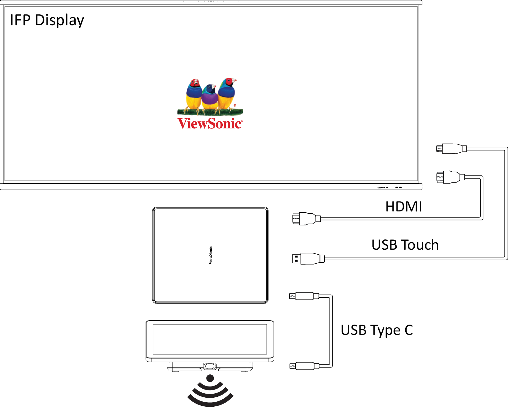
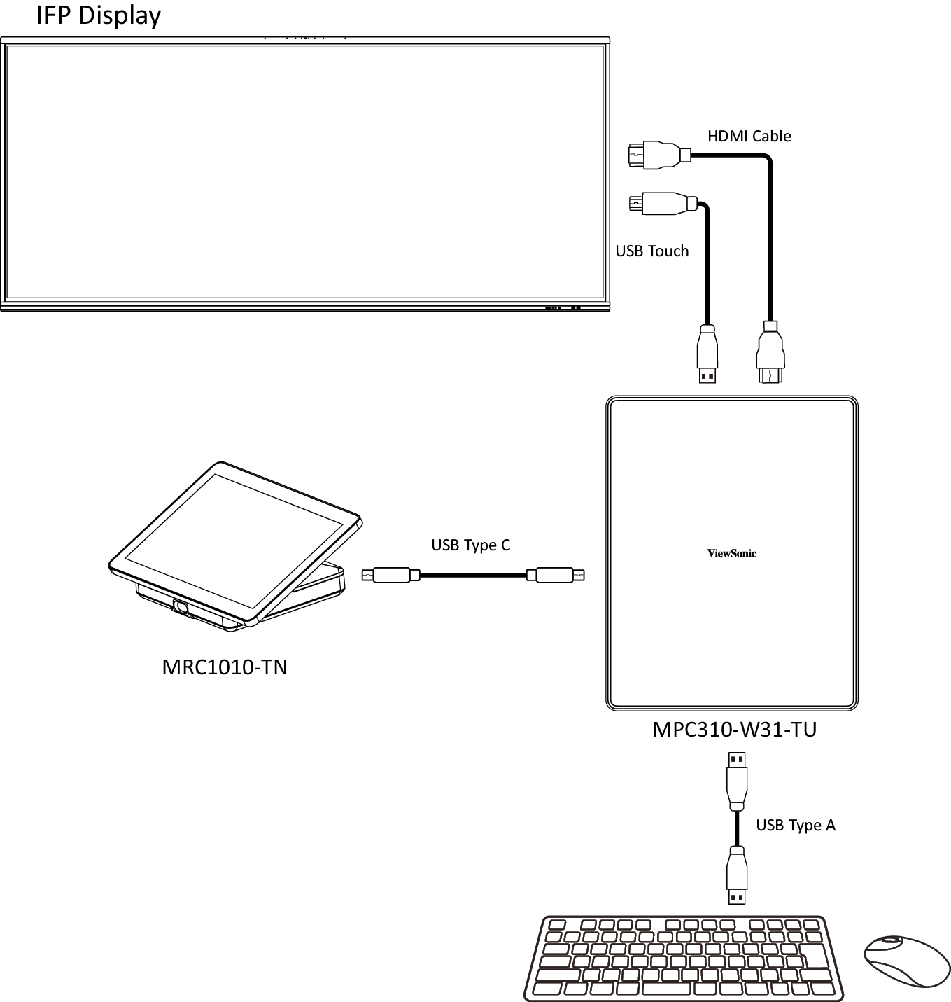
| No video output to the IFP display. | Verify that the HDMI cable has been plugged in properly into the IFP display's HDMI outlet. |
| Unable to display to the MRC1010-TN Touch console. | Verify that the USB Type C cable (Power delivery) has been plugged in properly into the MPC310-W31-TU Conferencing PC and MRC1010-TN Touch console USB Type C outlet. |
| How to Switch between the MTR account and the administrator account. | To switch from the MTR account to the administrator account:
To switch from the administrator account to the MTR account:
|
| How to set HDMI out resolution and refresh rate settings for 16:9 & 21:9 displays. | Switch from the MTR account to the administrator account:
IFP62 Series: 16:9, 3840 x 2160 @ 60 Hz
IFP105: 21:9, 3440 x 1440 @ 30 Hz
|
| MRC1010-TN Touch console built-in PIR sensor wake-up setting. | Switch from the MTR account to the administrator account:
|
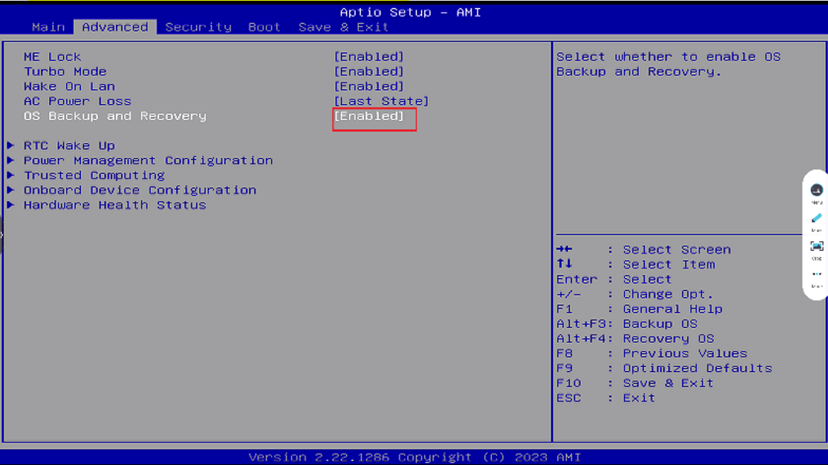
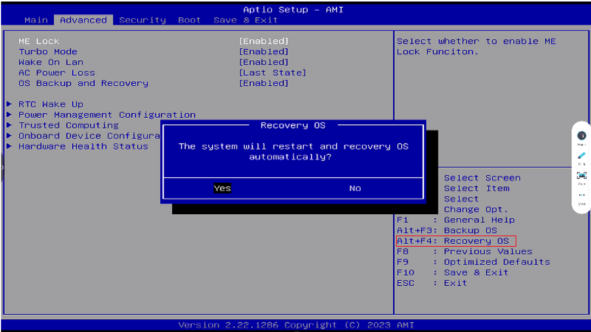
| How to restore the MTR system to original factory settings. |
|
Compliance Information
This section addresses all connected requirements and statements regarding regulations. Confirmed corresponding applications shall refer to nameplate labels and relevant markings on the unit.
FCC Compliance Statement
Contains FCC ID: TX2-RTL8852BE
This device complies with part 15 of FCC Rules. Operation is subject to the following two conditions: (1) this device may not cause harmful interference, and (2) this device must accept any interference received, including interference that may cause undesired operation. This equipment has been tested and found to comply with the limits for a Class B digital device, pursuant to part 15 of the FCC Rules.
These limits are designed to provide reasonable protection against harmful interference in a residential installation. This equipment generates, uses, and can radiate radio frequency energy, and if not installed and used in accordance with the instructions, may cause harmful interference to radio communications. However, there is no guarantee that interference will not occur in a particular installation. If this equipment does cause harmful interference to radio or television reception, which can be determined by turning the equipment off and on, the user is encouraged to try to correct the interference by one or more of the following measures:
- Reorient or relocate the receiving antenna.
- Increase the separation between the equipment and receiver.
- Connect the equipment into an outlet on a circuit different from that to which the receiver is connected.
- Consult the dealer or an experienced radio/TV technician for help.
FCC Radiation Exposure Statement
This device complies with FCC: radiation exposure limits set forth for an uncontrolled environment. End users must follow the specific operating instructions for satisfying RF exposure compliance.
This transmitter must not be co-located or operating in conjunction with any other antenna or transmitter. This device should be installed and operated with a minimum distance of 20 centimeters between the radiator and your body.
The user manual or instruction manual for an intentional or unintentional radiator shall caution the user that changes or modifications not expressly approved by the Party responsible for compliance could void the user’s authority to operate the equipment.
Industry Canada Statement
Contains IC ID: 6317A-RTL8852BE
CAN ICES(B) / NMB(B)
This Class B digital apparatus complies with Canadian ICES-003.
Cet appareil numérique de la classe B est conforme à la norme NMB-003 du Canada.
This device complies with Industry Canada license-exempt RSS standard(s): Operation is subject to the following Two conditions:(1) this device may not cause interference, and (2) this device must accept any interference, including interference that may cause undesired operation of the device.
Le présent appareil est conforme aux CNR d’Industrie Canada applicables aux appareils radio exempts de licence. L’exploitation est autorisée aux deux conditions suivantes : (1) l’appareil ne doit pas produire de brouillage, et (2) l’utilisateur de l’appareil doit accepter tout brouillage radioélectrique subi, même si le brouillage est susceptible d’en compromettre le fonctionnement.
Country Code Statement
For product available in the USA/Canada market, only channel 1~11 can be operated. Selection of other channels is not possible.
Pour les produits disponibles aux États-Unis/Canada du marché, seul le canal 1 à 11 peuvent être exploités. Sélection d’autres canaux n’est pas possible.
IC Radiation Exposure Statement
This device complied with IC RSS-102 radiation exposure limits set forth for an uncontrolled environment. This device should be installed and operated with minimum distance 20 cm between the radiator & your body.
Cet équipement est conforme aux limits d’exposition aux rayonnements IC établies pour un environnement non contrôlê. Cet équipement do it être installé et utilize avec un minimum de 20cm de distance entre la source de rayonnement et votre corps.
Caution:
(i) The device for operation in the band 5150-5250 MHz is only for indoor use to reduce the potential for harmful interference to co-channel mobile satellite systems;
(ii) for devices with detachable antenna(s), the maximum antenna gain permitted for devices in the bands 5250-5350 MHz and 5470-5725 MHz shall be such that the equipment still complies with the e.i.r.p. limit;
(iii) for devices with detachable antenna(s), the maximum antenna gain permitted for devices in the band 5725-5850 MHz shall be such that the equipment still complies with the e.i.r.p. limits as appropriate.
CE Conformity for European Countries
The device complies with the EMC Directive 2014/30/EU and Low Voltage Directive 2014/35/EU. https://www.viewsonicglobal.com/public/products_download/safety_compliance/acc/VS18617_CE_DOC.pdf?pass.
The following information is only for EU-member states:
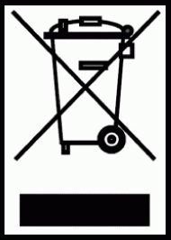
The mark shown to the right is in compliance with the Waste Electrical and Electronic Equipment Directive 2012/19/EU (WEEE). The mark indicates the requirement NOT to dispose of the equipment as unsorted municipal waste, but use the return and collection systems according to local law.
Batteries may not be disposed in trash or household recycling collection bins intended to receive other non-hazardous waste and/or recyclable materials. Please use the public collection system to return, recycle, or treat them in compliance with the local regulations. This product may contain button batteries, please keep it away from children.
BSMI /NCC Statement
限用物質含有情況標示 依檢驗標準CNS15663之規定將限用物質含有情況標示於商品之本體、包 裝、標貼、或說明書。 限用物質含有情況標示請參考下列網址:
VS19796(MPC310-W31-TU,MPC510-W53-TU,MPC710-W75-TU) https://www.viewsonicglobal.com/public/products_download/safety_compliance/acc/VS19796_BSMI_RoHS.pdf
VS19799(MRC1010-TN) https://www.viewsonicglobal.com/public/products_download/safety_compliance/acc/VS19799_BSMI_RoHS.pdf
NCC聲明
- 取得審驗證明之低功率射頻器材,非經核准,公司丶商號或使用者均不得擅自變更頻率、加大功率或變更原設計之特性及功能。低功率射頻器材之使用不得影響飛航安全及干擾合法通信;經發現有干擾現象時,應立即停用,並改善至無干擾時方得繼續使用。前述合法通信,指依電信管理法規定作業之無線電通信。低功率射頻器材須忍受合法通信或工業丶科學及醫療用電波輻射性電機設備之干擾。
- 應避免影響附近雷達系統之操作。
- 高增益指向性天線只得用於固定式點對點系統。
Declaration of RoHS2 Compliance
This product has been designed and manufactured in compliance with Directive 2011/65/EU of the European Parliament and the Council on restriction of the use of certain hazardous substances in electrical and electronic equipment (RoHS2 Directive) and is deemed to comply with the maximum concentration values issued by the European Technical Adaptation Committee (TAC) as shown below:
| Substance | Proposed Maximum Concentration | Actual Concentration |
|---|---|---|
| Lead (Pb) | 0.1% | < 0.1% |
| Mercury (Hg) | 0.1% | < 0.1% |
| Cadmium (Cd) | 0.01% | < 0.01% |
| Hexavalent Chromium (Cr6⁺) | 0.1% | < 0.1% |
| Polybrominated biphenyls (PBB) | 0.1% | < 0.1% |
| Polybrominated diphenyl ethers (PBDE) | 0.1% | < 0.1% |
| Bis (2-ethylhexyl) phthalate (DEHP) | 0.1% | < 0.1% |
| Butyl benzyl phthalate (BBP) | 0.1% | < 0.1% |
| Dibutyl phthalate (DBP) | 0.1% | < 0.1% |
| Diisobutyl phthalate (DIBP) | 0.1% | < 0.1% |
Certain components of products as stated above are exempted under the Annex III of the RoHS2 Directives as noted below. Examples of exempted components are:
- Copper alloy containing up to 4% lead by weight.
- Lead in high melting temperature type solders (i.e. lead-based alloys containing 85% by weight or more lead).
- Electrical and electronic components containing lead in a glass or ceramic other than dielectric ceramic in capacitors, e.g. piezoelectronic devices, or in a glass or ceramic matrix compound.
- Lead in dielectric ceramic in capacitors for a rated voltage of 125V AC or 250V DC or higher.
Indian Restriction of Hazardous Substances
Restriction on Hazardous Substances statement (India). This product complies with the “India E-waste Rule 2011” and prohibits use of lead, mercury, hexavalent chromium, polybrominated biphenyls or polybrominated diphenyl ethers in concentrations exceeding 0.1 weight % and 0.01 weight % for cadmium, except for the exemptions set in Schedule 2 of the Rule.
Product Disposal at End of Product Life
ViewSonic® respects the environment and is committed to working and living green. Thank you for being part of Smarter, Greener Computing. Please visit the ViewSonic® website to learn more.
USA & Canada
https://www.viewsonic.com/us/go-green-with-viewsonic
Europe
https://www.viewsonic.com/eu/environmental-social-governance/recycle
Taiwan
https://recycle.moenv.gov.tw
For EU users, please contact us for any safety/accident issue experienced with this product:
| ViewSonic Europe Limited Haaksbergweg 75 1101 BR Amsterdam Netherlands | |
| +31 (0) 650608655 | |
| EPREL@viewsoniceurope.com | |
| https://www.viewsonic.com/eu/ |
Copyright Information
Copyright© ViewSonic® Corporation, 2024. All rights reserved.
Macintosh and Power Macintosh are registered trademarks of Apple Inc.
Microsoft, Windows, and the Windows logo are registered trademarks of Microsoft Corporation in the United States and other countries.
ViewSonic® and the three birds logo are registered trademarks of ViewSonic® Corporation.
VESA is a registered trademark of the Video Electronics Standards Association. DPMS, DisplayPort, and DDC are trademarks of VESA.
Disclaimer: ViewSonic® Corporation shall not be liable for technical or editorial errors or omissions contained herein; nor for incidental or consequential damages resulting from furnishing this material, or the performance or use of this product.
In the interest of continuing product improvement, ViewSonic® Corporation reserves the right to change product specifications without notice. Information in this document may change without notice.
No part of this document may be copied, reproduced, or transmitted by any means, for any purpose without prior written permission from ViewSonic® Corporation.
MPC310-W31-TU_MRC1010-TN_UG_ENG_1a_20240612
Customer Service Contact Information
For technical support or product service, see the table below or contact your reseller.
- Note: You will need the product’s serial number, which is located on the rear of the monitor by the I/O ports.
Asia Pacific & Africa
| Country / Region | Website |
|---|---|
| Australia | https://viewsonic.com/au/ |
| Bangladesh | https://www.viewsonic.com/bd/ |
| 中囯(China) | https://www.viewsonic.com.cn |
| 香港 (繁體中文) | https://www.viewsonic.com/hk/ |
| Hong Kong (English) | https://www.viewsonic.com/hk-en/ |
| India | https://www.viewsonic.com/in/ |
| Indonesia | https://www.viewsonic.com/id/ |
| Israel | https://www.viewsonic.com/il/ |
| 日本 (Japan) | https://www.viewsonic.com/jp/ |
| Korea | https://www.viewsonic.com/kr/ |
| Malaysia | https://www.viewsonic.com/my/ |
| Middle East | https://www.viewsonic.com/me/ |
| Myanmar | https://www.viewsonic.com/mm/ |
| Nepal | https://www.viewsonic.com/np/ |
| New Zealand | https://www.viewsonic.com/nz/ |
| Pakistan | https://www.viewsonic.com/pk/ |
| Philippines | https://www.viewsonic.com/ph/ |
| Singapore | https://www.viewsonic.com/sg/ |
| 臺灣 (Taiwan) | https://www.viewsonic.com/tw/ |
| ประเทศไทย (Thailand) | https://www.viewsonic.com/th/ |
| Việt Nam | https://www.viewsonic.com/vn/ |
| South Africa & Mauritius | https://www.viewsonic.com/za/ |
Americas
| Country / Region | Website |
|---|---|
| United States | https://www.viewsonic.com/us/ |
| Canada | https://www.viewsonic.com/us/ |
| Latin America | https://www.viewsonic.com/la/ |
Europe
| Country / Region | Website |
|---|---|
| Europe | https://www.viewsonic.com/eu/ |
| France | https://www.viewsonic.com/fr/ |
| Deutschland | https://www.viewsonic.com/de/ |
| Қазақстан | https://www.viewsonic.com/kz/ |
| Россия | https://www.viewsonic.com/ru/ |
| España | https://www.viewsonic.com/es/ |
| Türkiye | https://www.viewsonic.com/tr/ |
| Україна | https://www.viewsonic.com/ua/ |
| United Kingdom | https://www.viewsonic.com/uk/ |


