VB-STND-008
Package Contents

| Letter | Quantity | Description | Note |
|---|---|---|---|
| A | 2 | Bolts | M6 x 14mm |
| B | 6 | Nuts | M8 |
| C | 4 | Bolts | M5 x 25mm |
| D | 4 | Bolts | M6 x 25mm |
| E | 4 | Bolts | M8 x 25mm |
| F | 4 | Bolts | M4 x 8mm |
| G | 1 | Hex Tool | 4mm |
| H | 1 | Wrench | |
| I | 4 | Caster Covers | Left Covers (x2) Right Covers (x2) |
| J | 2 | Attachable Cord Clamps | |
| K | 1 | Control Pad | |
| L | 1 | USB Type A to USB Type A cable |
|
| M | 2 | Trolley Bases | |
| N | 2 | Mounting Brackets | |
| O | 1 | Power Extension Cord | |
| P | 1 | Power Cord | |
| Q | 1 | Keyboard Tray |
Product Overview
Front and Side View
-
 Front View
 -
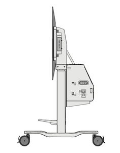 Side View


I/O Ports and Controls

| Number | Port | Description |
|---|---|---|
| 1 | USB A [1] | USB A Port |
| 2 | Lift Up/Down, Tilt Up/Down Buttons | Adjust Lift Height and Tilt Angle |
| 3 | RJ45 [2] | RJ45 Port |
| 4 | AC Out | Power Output Socket |
| 5 | AC In | Power Input Socket |
Control Pad

Assembling the Product
Step 1 - Connect the Trolley Body and Base
- Prepare the following items:


- Align the three holes on the Trolley Base (M) to the bolts underneath the Trolley Body. Using the wrench (H), secure the Trolley Base to the Trolley Body with the nuts (B).

- Ensure all nuts are tightened properly on the assembled Trolley Cart.


Step 2 - Attach the Mounting Brackets to the IFP
Attach the Mounting Brackets (N) to the IFP. Depending on the size of the IFP, use either M5 (C), M6 (D), or M8 (E) bolts. Refer to the IFP user guide to find the right bolt size.

Step 3 - Attach the Keyboard Tray
Attach the Keyboard Tray (Q) to the middle support.

Step 4 - Secure the IFP to the Trolley Cart
- Lift the IFP up and hook the Mounting Brackets onto the Trolley Cart.

- Secure the Mounting Brackets to the Trolley Cart with two M6 x 14mm bolts (A).

Step 5 - Removing the Protective Cover and Installing a Chrome Box
- Unscrew the M4 x 8mm bolts (F) and remove the Protective Cover from the Trolley Cart. Attach the Chrome Box onto the Trolley Cart.


- Reattach the Protective Cover onto the Trolley Cart with the M4 x 8mm bolts, covering the Chrome Box.

- Ensure all parts are accurately and securely held together, as shown in the diagrams below.


Step 6 - Move and Park the Trolley Cart
After moving the Trolley Cart to desired location, push down on the wheel brakes to lock the Trolley Cart in place.

Step 7 - Install the Caster Covers
Install the Caster Covers (I) to further secure the Trolley Cart in place.
- Ensure the wheels are aligned with the Trolley Cart.

- Slide the Caster Covers over the wheels.

Storing the Caster Covers
The Caster Covers are magnetic. Refer to the diagram below for the position of the magnet.

When moving the Trolley Cart, attach the Caster Covers to the left and right supports.

Connecting to Power
- Connect the power cord to the Trolley Cart.
- Plug the power cord plug into a power outlet.
- Use the cord clamp to secure the cords in place.


Connecting to the Control Pad
Connect the Control Pad to the Trolley Cart via the RJ45 Port.

Connecting to the IFP
- Connect the IFP to the AC power output of the Trolley Cart.
- Connect the USB Type A cord to both the IFP and the Trolley Cart.

Overview
This section will introduce how to adjust the height and angle of the Trolley Cart by using the Lift/Tilt function.
There are three ways to control the Lift:
- Using the Trolley Cart Control Panel.
- Using the Control Pad.
- Using the Application on the IFP.
Using the Trolley Cart Control Panel or Control Pad

| Item | Icon | Description |
|---|---|---|
| Lift Up | Press and hold to raise the VB-STND-008. | |
| Lift Down | Press and hold to lower the VB-STND-008. | |
| Tilt Up | Press and hold to tilt the VB-STND-008 backwards. | |
| Tilt Down | Press and hold to tilt the VB-STND-008 forwards. |
Using the Application on the IFP
- Select the More Options Icon (...) from the side tool bar.
- Select Trolley Cart Control.
- Adjust the height of the Trolley Cart accordingly.


| Item | Icon | Description |
|---|---|---|
| Lift Up | Press and hold to raise the VB-STND-008. | |
| Lift Down | Press and hold to lower the VB-STND-008. | |
| Tilt Down | Press and hold to tilt the VB-STND-008 forwards. | |
| Tilt Up | Press and hold to tilt the VB-STND-008 backwards. | |
| Preset Position 1 | Adjust the Lift to desired height. Long press to save current height as Preset Position 1. | |
| Preset Position 2 | Adjust the Lift to desired height. Long press to save current height as Preset Position 2. | |
| Preset Position 3 | Adjust the Lift to desired height. Long press to save current height as Preset Position 3. | |
| Stop | When using the Preset Position function, the Lift will adjust to the saved height. If you want to stop this process, press to stop height adjustment and motor movement. |
Technical Specifications
| Item | Specifications |
|---|---|
| Model No. | VS18670 |
| P/N | VB-STND-008 |
| Swivel | 360° by 4” silent wheel |
| Height Adjust Range | 560 mm (22.05 in) |
| Wall Mount Pattern | 800 x 600 mm max. |
| Material | Aluminum Alloy, Plastic, Steel |
| Wall Mount Loading | 75 kg max. (165 lbs max.) |
| Keyboard Tray Loading | 10 kg max. (22 lbs max.) |
| Input Voltage | AC 100v ~ 240v 50/60Hz 10A |
| Output Voltage (for IFP Power) | AC 100v ~ 240v 50/60Hz 6A |
| Control Panel | Trolley Cart: Lift Up/Down, Tilt Up/Down Control Pad: Lift Up/Down, Tilt Up/Down IFP App: Lift Up/Down, Tilt Up/Down, Preset Position 1~3, Stop |
| Dimensions (W x H x D) |
1248.9 x (1330.7 ~ 1890.7) x 706 mm (49.17 x (52.4 ~ 74.44) x 28.19 in) |
| Weight | 65 kg (143 lb) |
| Motor Speed | 33 mm/second (1.3 in/second) |
| Lift Safety Sensor | 11 ~ 15 kg (24.25 ~ 33.07 lbs) |
| Tilt Angle | 0° ~ 90° |
Troubleshooting Common Problems
This section describes some common problems that you may experience when using the Trolley Cart.
| Problem or Issue | Possible Solutions |
|---|---|
| No power |
|
| Lift is not moving |
|
Compliance Information
This section addresses all connected requirements and statements regarding regulations. Confirmed corresponding applications shall refer to nameplate labels and relevant markings on the unit.
FCC Compliance Statement
This device complies with part 15 of FCC Rules. Operation is subject to the following two conditions: (1) this device may not cause harmful interference, and (2) this device must accept any interference received, including interference that may cause undesired operation. This equipment has been tested and found to comply with the limits for a Class B digital device, pursuant to part 15 of the FCC Rules.
These limits are designed to provide reasonable protection against harmful interference in a residential installation. This equipment generates, uses, and can radiate radio frequency energy, and if not installed and used in accordance with the instructions, may cause harmful interference to radio communications. However, there is no guarantee that interference will not occur in a particular installation. If this equipment does cause harmful interference to radio or television reception, which can be determined by turning the equipment off and on, the user is encouraged to try to correct the interference by one or more of the following measures:
- Reorient or relocate the receiving antenna.
- Increase the separation between the equipment and receiver.
- Connect the equipment into an outlet on a circuit different from that to which the receiver is connected.
- Consult the dealer or an experienced radio/TV technician for help.
Industry Canada Statement
CAN ICES-003(B) / NMB-003(B)
CE Conformity for European Countries
The device complies with the EMC Directive 2014/30/EU and Low Voltage Directive 2014/35/EU.
The following information is only for EU-member states:
The mark shown to the right is in compliance with the Waste Electrical and Electronic Equipment Directive 2012/19/EU (WEEE). The mark indicates the requirement NOT to dispose of the equipment as unsorted municipal waste, but use the return and collection systems according to local law.
Declaration of RoHS2 Compliance
This product has been designed and manufactured in compliance with Directive 2011/65/EU of the European Parliament and the Council on restriction of the use of certain hazardous substances in electrical and electronic equipment (RoHS2 Directive) and is deemed to comply with the maximum concentration values issued by the European Technical Adaptation Committee (TAC) as shown below.
| Substance | Proposed Maximum Concentration | Actual Concentration |
|---|---|---|
| Lead (Pb) | 0.1% | < 0.1% |
| Mercury (Hg) | 0.1% | < 0.1% |
| Cadmium (Cd) | 0.01% | < 0.01% |
| Hexavalent Chromium (Cr6⁺) | 0.1% | < 0.1% |
| Polybrominated biphenyls (PBB) | 0.1% | < 0.1% |
| Polybrominated diphenyl ethers (PBDE) | 0.1% | < 0.1% |
| Bis (2-ethylhexyl) phthalate (DEHP) | 0.1% | < 0.1% |
| Butyl benzyl phthalate (BBP) | 0.1% | < 0.1% |
| Dibutyl phthalate (DBP) | 0.1% | < 0.1% |
| Diisobutyl phthalate (DIBP) | 0.1% | < 0.1% |
Certain components of products as stated above are exempted under the Annex III of the RoHS2 Directives as noted below. Examples of exempted components are:
- Copper alloy containing up to 4% lead by weight.
- Lead in high melting temperature type solders (i.e. lead-based alloys containing 85% by weight or more lead).
- Electrical and electronic components containing lead in a glass or ceramic other than dielectric ceramic in capacitors, e.g. piezoelectronic devices, or in a glass or ceramic matrix compound.
- Lead in dielectric ceramic in capacitors for a rated voltage of 125 V AC or 250 V DC or higher.
Indian Restriction of Hazardous Substances
Restriction on Hazardous Substances statement (India). This product complies with the “India E-waste Rule 2011” and prohibits use of lead, mercury, hexavalent chromium, polybrominated biphenyls or polybrominated diphenyl ethers in concentrations exceeding 0.1 weight % and 0.01 weight % for cadmium, except for the exemptions set in Schedule 2 of the Rule.
Product Disposal at End of Product Life
ViewSonic® respects the environment and is committed to working and living green. Thank you for being part of Smarter, Greener Computing. Please visit the ViewSonic® website to learn more.
USA & Canada:
https://www.viewsonic.com/us/go-green-with-viewsonic
Europe:
https://www.viewsonic.com/eu/environmental-social-governance/recycle
Taiwan:
https://recycle.moenv.gov.tw/
For EU users, please contact us for any safety/accident issue experienced with this product:
| ViewSonic Europe Limited Haaksbergweg 75 1101 BR Amsterdam Netherlands | |
| +31 (0) 650608655 | |
| EPREL@viewsoniceurope.com | |
| https://www.viewsonic.com/eu/ |
Copyright Information
Copyright© ViewSonic® Corporation, 2022. All rights reserved.
Macintosh and Power Macintosh are registered trademarks of Apple Inc.
Microsoft, Windows, and the Windows logo are registered trademarks of Microsoft Corporation in the United States and other countries.
ViewSonic® and the three birds logo are registered trademarks of ViewSonic® Corporation.
VESA is a registered trademark of the Video Electronics Standards Association. DPMS, DisplayPort, and DDC are trademarks of VESA.
Disclaimer: ViewSonic® Corporation shall not be liable for technical or editorial errors or omissions contained herein; nor for incidental or consequential damages resulting from furnishing this material, or the performance or use of this product.
In the interest of continuing product improvement, ViewSonic® Corporation reserves the right to change product specifications without notice. Information in this document may change without notice.
No part of this document may be copied, reproduced, or transmitted by any means, for any purpose without prior written permission from ViewSonic® Corporation.
VB-STND-008_UG_ENG_1b_20231012
Using the ViewBoard Stand Safely
Please read the following Safety Precautions before you start using the device.
- Keep this user guide in a safe place for later reference.
- Read all warnings and follow all instructions.
- To prevent damage, avoid any physical pressure, vibration, or immersion during transportation, possession, or installation of the product.
- Always place the product on a flat, stable surface.
- Avoid contacting any liquids, gas, or corrosive materials with the shell of the product.
- This product has no parts which can be repaired by the user. Any damage caused by the user's own disassembly is not covered by warranty.
- This product is special use with ViewSonic® commercial Touch Display only, Use with other model is capable of resulting in instability causing possible injury.
- This product is only compatible with panels up to a maximum size of 86”.
- The maximum weight loading of this product is 75 kg (165 lb).
- Avoid the following to prevent the personal injury and/or equipment damage:
- Children MUST NOT operate plant or machinery.
- KEEP AWAY from moving parts to avoid injury.
- DO NOT move the cart with the lift in the highest position.
- DO NOT push the cart from the front or attempt to lift it.
- DO NOT move the cart by pushing on the IFP/panel.
- DO NOT move the cart over cords or uneven, dirty, and/or slopes.
