LDS135-153 Full Guide: Difference between revisions
No edit summary |
No edit summary |
||
| Line 29: | Line 29: | ||
[[Category:LDS135-153]] | [[Category:LDS135-153]] | ||
[[Category:Archive]] | |||
Latest revision as of 09:03, 23 December 2025
Package Contents
| Item | Quantity | Note | |
|---|---|---|---|
| LED Display with Motorized Trolley Cart |  |
1 | |
| Quick Start Guide |  |
1 | |
| Accessory Box |  |
1 |
|
| Power Cable |  |
1 | |
| Vacuum Suction Tool |  |
1 | |
| T-Type Wrench |  |
1 | |
- This product is packed in an air transport box.
- Due to the size and weight, it is recommended that two or more people handle it.
Product Overview
Front Panel

Rear Panel

I/O Ports

| Number | Item | Port | Description |
|---|---|---|---|
| 1 | 
|
HDMI OUT | Extend content out to another display device. |
| 2 | 
|
Audio OUT | Audio output to an external speaker. |
| 3 |
|
Audio IN | Audio input from an external device. |
| 4 | 
|
S/PDIF Out | Multichannel sound via optical signals. |
| 5 | IR IN | Extend the IR Receiver. | |
| 6 | USB 2.0 | USB Reader (5V/1.5A). | |
| 7 | 
|
LAN | Standard RJ45 (10M/100M/1000M) Internet connection interface. |
| 8 |
|
HDMI IN 2.0 | High definition input: PIP/PBP ,connect to PC with HDMI output, set-top box, or other video device. |
| 9 |
|
HDMI IN 1.4 | High definition input: PIP/PBP ,connect to PC with HDMI output, set-top box, or other video device. |
| 10 |
|
HDMI IN 2.1 | High definition input: connect to PC with HDMI output, set-top box, or other video device. |
| 11 | 
|
RS-232 | Serial control port. |
Control Panel

| Number | Item | Description | |
|---|---|---|---|
| 1 | USB C | USB-C Reader (5V/2A) | |
| 2 | USB 2.0 | USB Reader (5V/1.5A) | |
| 3 | IR Receiver | Receiver for the Remote Control. | |
| 4 | Brightness | Press to cycle through brightness levels. | |
| 5 | Volume + | Increase the volume. | |
| 6 | Volume - | Decrease the volume. | |
| 7 | 
|
Input Select | Press to cycle through available input sources. |
| 8 | Stand-by | Press to enter Stand-by mode. | |
- Locking the Control Panel
- When the administrator does not want others to use the control panel, it can be locked by pressing 1168+OK on the remote control.
Remote Control Overview

| Number | Icon | Item | Description |
|---|---|---|---|
| 1 | Power | Power On/Off | |
| 2 | Home | Back to Home Screen | |
| 3 | Source | Input source selection | |
| 4 | HDMI 1/2 | Change to HDMI 1/2 input source | |
| 5 | Blank | Switch to a blank, black screen | |
| 6 | Brightness | Adjust the brightness level | |
| 7 | ▲/▼/◄ / ► | Directional buttons | |
| 8 | OK | Confirm the selection | |
| 9 | i | Enter the Information page | |
| 10 | Menu | Enter the Settings menu | |
| 11 | Return | Return to previous | |
| 12 | Play/Pause | Play/Pause content | |
| 13 | Forwards/Backwards | Move content forwards/backwards | |
| 14 | Volume Up/Down | Increase/decrease the volume level | |
| 15 | Numbers | Numeric input buttons | |
| 16 | . | Input key for a dot (.) | |
| 17 | Backspace/Clear | Delete key for text input | |
| 18 | Mute | Mute/Unmute |
Inserting Remote Control Batteries
The remote control is powered by two 1.5v "AAA" batteries.
To insert batteries into the remote control:
- Remove the cover on the rear of the remote control.
- Insert two “AAA” batteries, ensuring the “+” symbol on the battery matches the “+” on the battery post.
- Replace the cover by aligning it with the slot on the remote control and snapping the latch shut.
- WARNING: There is a risk of explosion if batteries are installed with incorrect polarity.
- It is recommended that you do not mix battery types.
- Avoid exposure to heat or steam.
- Do not allow water or other liquids to splash on the remote control. If the remote control becomes wet, wipe it dry immediately.
- Always dispose of old batteries in an environmentally friendly way. Contact your local government for more information on how to dispose of batteries safely.
- Locking the Remote Control
- When the administrator does not want others to control the remote control, it can be locked by pressing 1169+OK on the remote control.
Remote Control Receiver Range
The operating range of the remote control is shown here. It has an effective range of 20 feet (6 meters), 30° degrees left and right. Ensure there is nothing obstructing the remote control’s signal to the receiver.

Control Panel for Motorized Trolley Cart

- Instructions on Preset Lifting Height
- Initial preset lifting height: Three groups of preset data. The 1/2/3 keys (. , .. , ...) correspond to 0 cm / 25 cm / 65 cm height respectively.
- Erasing of preset height data: Height data can be stored for more than 10 years. When new parameters are set, old parameters will be automatically erased.
- How to preset height: at any height (unavailable under the reset and error status), the current height parameters can be preset into keys 1/2/3.
For example:Set 25 cm on the 2 key: 
Press the S key to display SET. 
Within 2 seconds, before SET disappears, press the 2 (..) key. 
When S-2 is displayed, the setting is over and will return to the previous display. 
- How to Use Preset Height
At any height (unavailable under the reset and error status), keys 1/2/3 may be used to quickly reach the preset height. If the current height has reached such preset height, no actions will be performed. - How to Change the Height
- Use the Up key to lift the display. The lift will automatically stop upon reaching the height limit. Please note, the Up key is a “click to act” key, i.e., upon releasing the key the lift will not immediately stop. Instead, it will slow down for a short distance then stop.
- Use the Down key to lower the display. The lift will automatically stop upon reaching the height limit. Please note, the Down key is a “click to act” key, i.e., upon releasing the key the lift will not immediately stop. Instead, it will slow down for a short distance then stop.


Handling and Moving the Flight Case

- During moving, handling, placing and transporting of flight cases, always keep the specified position up, no reversing, in order to prevent bumping and damage to the structure of the equipment and the display components.
- Before moving any flight case, pull up the brake locks of the four rollers at the bottom, guaranteeing the release of the brake status.

- Ensure that the ground is level, with the height difference less than 1.5 cm, and the ground can comfortably hold more than the weight of the entire equipment.
- During moving, at least two adults are needed.
- When storing the flight case, make sure the ground is level and that all four rollers are locked.
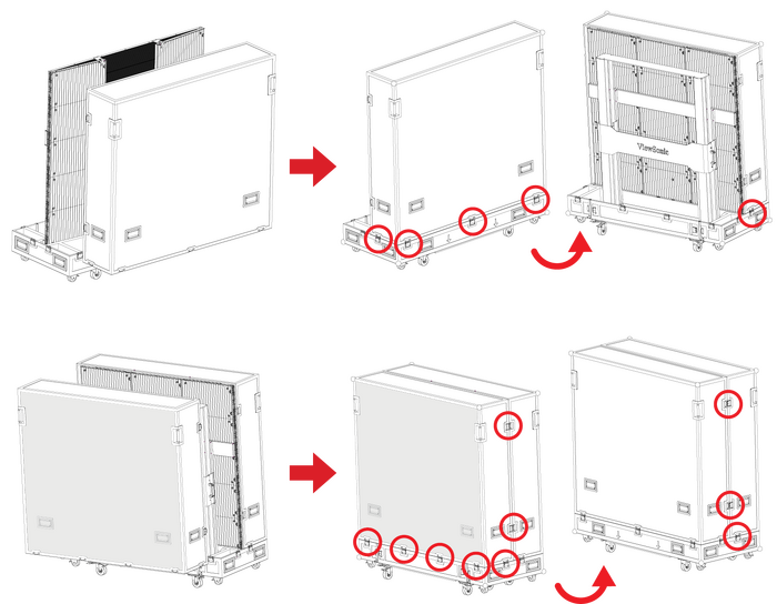
Unpacking the Operation
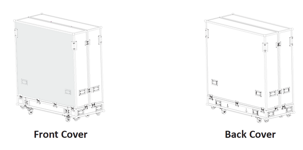
- After the flight case is moved to the designated location, open the flight case according to the sequence of Front Cover, Back Cover, Movable Plate and Bottom Plate. To distinguish the Front cover and Back cover, refer to the following diagram.
- As shown below, pull the handle of the lock-ups, and rotate the handle counterclockwise to unlock the ten lock-ups connecting the Front Cover with the Bottom Plate and the Back Cover.
Note: Ensure that each lock-up will not be interlocked.
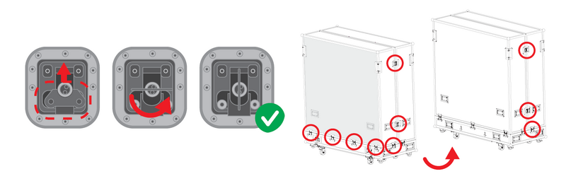
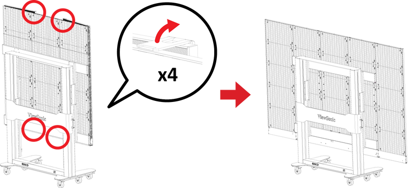
- Two people will need to grip the handles, as indicated by the red circles below, and pull. While lifting, keep the Front Cover level as it is moved to another location.
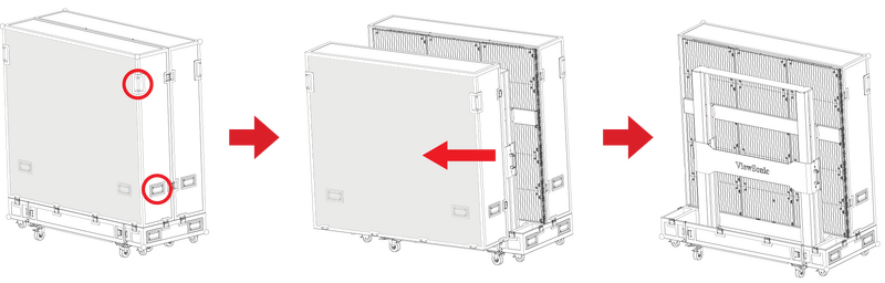
- As shown below, pull the handle of the lock-ups, and rotate the handle counterclockwise to unlock the five lock-ups connecting the Back Cover with the Bottom Plate.
Note: Ensure that each lock-up will not be interlocked.

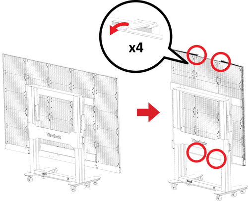
- Two people will need to grip the handles, as indicated by the red circles below, and pull. While lifting, lift off the Back Cover to another location, ensuring to keep the cover level.

- As shown in the red circles below, open the four lock-ups of the Movable plate at the bottom of the flight case. Lift the Movable plate while holding up the bottom of the flight case. Pull out the Movable plate from behind to separate.

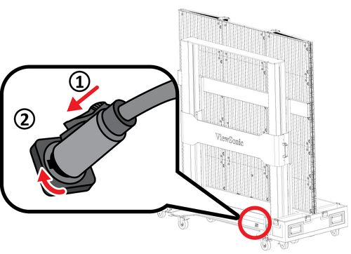
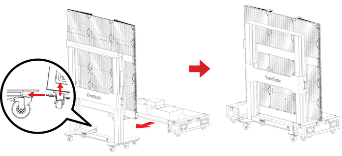
- Take the power cord out of the accessory box. Insert the flight plug into the female socket at the right of the base control box of the screen and rotate the plug 90° clockwise (as shown below).
Note: Ensure the plug is connected securely (a click should be heard). Insert the other end of the plug into a power socket. Ensure that the power socket meets the specifications and standards of the LED display screen (30A socket for 110V area, and 16A socket for 220V area).
- After the power cord is properly connected, the green light and digits on the control lifting plate of the base of the screen will be on. Press the 2 key (..) on the control box at the base, or continuously hold the “Up” key, to raise the screen and lift it from the cabinet.

- After the screen is raised to a certain height, pull out the Bottom Plate of the flight case from the front.

- Unlock the four top and bottom buckles, and open both side cabinets of the display.
- The display is now ready to power on.


Packing and Handling the Flight Case
- Turn off and close both side cabinets of the display, and lock the four buckles.
- Make sure that the display is turned off, and the Accessories box is placed in the grid corresponding to the Bottom Plate of the flight case. The Bottom Plate of the flight case, which shall be close to the ground, is clipped into the base of the display from the front as shown below.
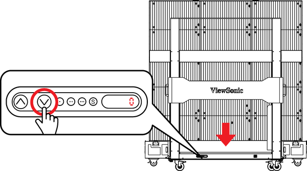
- Press the 1 key (.) on the control box at the base, or continuously hold the “Down” key, to lower the screen to the lowest position until it is inside the cart slot, as shown below:
- Make sure the display is turned off, then unplug the power cord from the power socket. Next, remove the flight plug by rotating it 90° counterclockwise. Finally, place the power cord into the Backup Box on the Bottom plate.

- Insert the Movable Plate from behind, as shown below, and tighten the four lock-ups connecting with the Bottom Plate.
Note: Ensure that the clips are engaged.
- Two people will need to lift the Back Cover of the flight case, aligning the Back Cover with the position of the lock-ups of the Bottom Plate. When aligned, rotate the five lock-ups clockwise to secure the connection with the Bottom Plate. Next, lift the Front Cover of the flight case onto the Bottom Plate, aligning the Front Cover with the position of the lock-ups. When aligned, rotate the 10 lock-ups clockwise to secure the connection between the Front Cover, the Bottom Plate, and Back Cover.
Note: Ensure that the lock-ups are engaged in place, and there are no obvious gaps.
- After the flight case is closed, at least two people will be needed to move the case to its storage or transport location. Ensure the brake locks are engaged on all six rollers upon reaching the case’s storage or transport location.
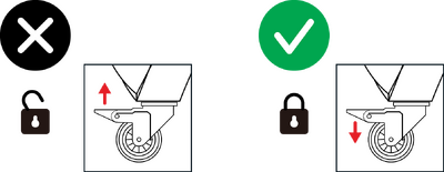 When storing the flight case, ensure the ground is level and that all six rollers are locked.


Making Connections
Connecting to Video
HDMI
Connect an HDMI cable from your external device to an HDMI IN port on the display.

HDMI Out
To output video via an external display device, connect an HDMI cable to the HDMI IN port of your external display device, and the other end to the HDMI OUT port of the display.

Audio Connection
The LED Display supports Audio In, Audio Out, and SPDIF.
Audio In

Aduio Out
To play audio from the display through an external speaker, connect one end of an audio cable to the external speaker, and the other end to the display's Audio Out port.

SPDIF
To play audio from the display through an external speaker, connect one end of an optical cable to the external speaker, and the other end to the display's SPDIF Out port.

RS-232 Control Connection
When you use a RS-232 serial cable to connect the display to an external computer or control system, certain functions can be controlled remotely, such as: power on and off, volume adjustment, input select, brightness, and more.

USB Connections
USB Type A
Plug the USB device or storage drive into a USB Type A (USB 2.0) port on the display’s control panel.

USB Type C
Plug the USB device or storage drive into the USB Type C port on the display’s control panel.

Network Connection
To connect to a network, connect an Ethernet cable to your network, then connect the other end to the LAN port of the display.

Power On/Off your LED Display

- Ensure the power cord is connected and plugged into a power outlet.
- Press the Power Switch to the ON position.
- Press the Power button to turn on the LED Display.
- To turn the LED display off, press the Power button again.
Home Screen

| Number | Item | Description |
|---|---|---|
| 1 | Main Menu | Access the Home Screen, APP Center, Settings, and Input Source. |
| 2 | Time of Day Indicator | The sky will change over the day between morning, noon, afternoon, and night. |
| 3 | Quick Access | Quick access to LAN, Wi-Fi, Brightness, and Power.
NOTE: Only supported by keyboard and mouse. |
| 4 | Date & Time | Automatic time adjustment, time zone selection, and 24-hour format can all be adjusted. The Date & Time can also be hidden from the Home Screen under: Settings > Display > Launcher Settings |
| 5 | ViewSonic Logo | The logo can be hidden from the Home Screen under:
Settings > Display > Launcher Settings |
Remote Control
The remote control can be used to easily navigate the Home Screen. When using the remote control, ensure it is kept within the IR receiver range as shown below:

Keyboard and Mouse
When connected to the USB Type-A port of the display, a keyboard and mouse can also be used to navigate the Home Screen.
The mouse pointer will appear as an orange dot on the display when used:

- The left mouse button will confirm actions.
- The right mouse button will go back to the previous layer.
- Keyboard shortcuts and hot keys are also supported, including: audio adjustment, mute, and back to the Home Screen.
APP Center
Installed applications will be in the App Center.

| Icon | Name | Description |
|---|---|---|
| Browser | Web browser | |
| Display | Wirelessly mirror your desktop | |
| EAirplay | AirPlay mirroring | |
| EnterpriseAgent | Device management | |
| File Manager | File explorer | |
| Manager | Remote device management | |
| Revel Digital Signage | Manage digital signage | |
| SureMDM Nix | Secure, monitor, and manage devices | |
| WPS Office | Create documents, spreadsheets, and presentations | |
| vCastReceiver | Receive casted content from devices | |
| vSweeper | Clear up storage space |
Input Source

The display supports eight input sources: Home, HDMI 1,HDMI 2, HDMI 3, HDMI 4, HDMI 5, HDMI 6, and USB C.
Settings
Adjust and view the display's settings.


| Menu | Description |
|---|---|
| Network & Internet | View and adjust Wi-Fi, Ethernet, and Potable Hotspot. |
| Connected Devices | View and adjust Connected Devices. |
| Apps & Notifications | View and adjust App Info., App Permissions, and Default Apps. |
| Display | View and adjust Brightness Level, Ambient Light Sensor, Font Size, Startup & Shutdown, Input Setting, and Launcher Settings. |
| Sound | View and adjust Media Volume. |
| Storage | View and adjust Device Storage. |
| System | View and adjust Languages & Input, Date & Time, Dehumidification, Reset, and About Device. |
| Upgrade | View and adjust OTA Upgrade and Local Update. |
Settings Menu Tree
Network & Internet
| Sub-menu | Menu Option | ||
|---|---|---|---|
| Wi-Fi | Wi-Fi | On | |
| Off | |||
| Wi-Fi List | Add Network | ||
| Wi-Fi Preference | Open Network Notification | On | |
| Off | |||
| Keep Wi-Fi On During Sleep | |||
| Advanced | |||
| Ethernet | Ethernet IP Mode | DHCP | |
| STATIC | |||
| Ethernet Details | |||
| Portable Hotspot | Portable Wi-Fi Hotspot | On | |
| Off | |||
Connected Devices
| Sub-menu | Menu Option |
|---|---|
| Connected Devices | On |
| Off | |
| Device Name | ViewSonic DvLED |
Apps
| Sub-menu | Menu Option | |
|---|---|---|
| App Info. | Installed Apps | Disable |
| Force Stop | ||
| App Permissions | Calendar | |
| Location | ||
| Microphone | ||
| Storage | ||
| Default Apps | Browser | |
| Home | ||
Display
| Sub-menu | Menu Option | ||
|---|---|---|---|
| Brightness Level | (-/+, 1~8) | ||
| Ambient Light Sensor | On | ||
| Off | |||
| Font Size | (-/+, 1~4) | ||
| Startup & Shutdown | Splash Screen | Default | |
| ViewSonic | |||
| Black | |||
| Blue | |||
| Last Shutdown Channel | On | ||
| Off | |||
| Default Startup Channel | Home | ||
| HDMI 1 | |||
| HDMI 2 | |||
| HDMI 3 | |||
| HDMI 4 | |||
| HDMI 5 | |||
| USB C | |||
| HDMI 6 | |||
| APP (Display) | |||
| APP (vCastReceiver) | |||
| Standby Mode | Hibernate | ||
| Sleep | |||
| Splash Screen | ViewSonic | ||
| Black | |||
| Blue | |||
| Input Setting | Input Alias | HDMI 1 | Display |
| Hide | |||
| HDMI 2 | Display | ||
| Hide | |||
| HDMI 3 | Display | ||
| Hide | |||
| HDMI 4 | Display | ||
| Hide | |||
| HDMI 5 | Display | ||
| Hide | |||
| USB C | Display | ||
| Hide | |||
| HDMI 6 | Display | ||
| Hide | |||
| Signal Source Detect | Enable | ||
| Disable | |||
| Launcher Settings | ViewSonic Logo | On | |
| Off | |||
| Date & Time | On | ||
| Off | |||
| Theme | |||
| Other Display Settings | Custom Resolution | Width | |
| Height | |||
| Custom DPI | (-/+, 100~240) | ||
| Custom Wallpaper | |||
| Boot Logo Settings | |||
Sound
| Sub-menu | Menu Option | ||
|---|---|---|---|
| Media Volume | (-/+, 0~100) | ||
Storage
| Sub-menu | Menu Option | ||
|---|---|---|---|
| Device Storage | Internal Shared Storage | Storage Manager | On |
| Off | |||
| Photos & Videos | |||
| Music & Audio | |||
| Games | |||
| Movie & TV | |||
System
| Sub-menu | Menu Option | ||
|---|---|---|---|
| Language & Input | Languages | English | |
| French | |||
| Spanish | |||
| German | |||
| Russian | |||
| Dutch | |||
| 繁体中文 | |||
| 简体中文 | |||
| Turkish | |||
| Arabic | |||
| Virtual Keyboard | Remote Control Input Method | ||
| Manage Keyboards | |||
| Timer Setting | Shutdown Time | Repeat | Off |
| Once | |||
| Everyday | |||
| Time | |||
| Power On Time | Repeat | Off | |
| Once | |||
| Everyday | |||
| Time | |||
| Sleep Timer | Off/1/10/20/30/40/50/60/90/120 minute(s) | ||
| Power Saving | On | ||
| Off | |||
| Standby Mode | Hibernate | ||
| Sleep | |||
| Date & Time | Automatic Date & Time | On | |
| Off | |||
| Select Time Zone | |||
| Use 24-hour Format | On | ||
| Off | |||
| Dehumidification | Settings | On | |
| Off | |||
| Automatic Reminders | On | ||
| Off | |||
| Begin Dehumidification Now | On | ||
| Off | |||
| Scheduled | On | ||
| Off | |||
| Reset | Network Settings Reset | ||
| Reset App Preferences | |||
| Factory Data Reset | |||
| About Device | Status | ||
| Legal Information | |||
| Model | |||
| Kernel Version | |||
| Build Number | |||
| Total Time | |||
Upgrade
| Sub-menu | Menu Option |
|---|---|
| OTA Upgrade | OTA Cloud Server |
| Local Update | sda1 |
| SDcard |
Network & Internet

| Sub-menu | Description |
|---|---|
| Wi-Fi |
|
| Ethernet | Select Ethernet to enable/disable Ethernet, review DNS, and IP mode.
|
| Portable Hotspot | Enable/disable Portable Wi-Fi Hotspot under Portable Hotspot.
|


Connected Devices

Enable/disable device connection, review connected devices, and search and connect to other devices.
Apps & Notifications

| Sub-menu | Description |
|---|---|
| App Info. |
|
| App Permissions | Select App Permissions to manage various application permissions.
|
| Default Apps | Select your default applications.
|


Display

| Sub-menu | Description |
|---|---|
| Brightness Level | Adjust the brightness level by eight levels.
|
| Ambient Light Sensor | Detects ambient light and adjusts brightness levels automatically. |
| Font Size | Preview and adjust the font size on the display.
|
| Startup & Shutdown |
Startup Channel
Standby Mode
Splash Screen |
| Input Setting |
Input Alias Switch Signal Source Detect U Disk Detect |
| Launcher Settings |
ViewSonic Logo Date & Time Theme
|
| Other Display Settings | Adjust the Resolution, DPI, wallpaper and other display settings. |


Sound

| Sub-menu | Description |
|---|---|
| Media Volume | Adjust the volume level of the display. |
Storage

| Sub-menu | Description |
|---|---|
| Internal Shared Storage | Internal storage allocation. |
System

| Sub-menu | Description |
|---|---|
| Languages & Input |
Languages Virtual Keyboard |
| Timer Setting |
Shutdown Time Repeat Power ON Time Repeat Sleep Timer Power Saving Standby Mode |
| Date & Time |
Automatic Date & Time Select Time Zone Use 24-hour Format |
| Dehumidification |
Start and adjust dehumidification settings.
|
| Reset |
Network Settings Reset Reset App Preferences Factory Data Reset |
| About Device | View information about the display.
|


Upgrade

| Sub-menu | Description |
|---|---|
| OTA Upgrade |
Auto Update Manual Update
|

On-Screen Display (OSD) Menu Operation
Use the On-Screen Display (OSD) Menu to adjust various settings.

To open and operate the OSD Menu:
- Press the MENU button on the remote control.
- Press ▼/▲/◄/► on the remote control to select menu items or adjust values.
- Press OK to confirm your selection.
- Press the RETURN button to go back to the previous menu level.
- Press the MENU button to exit the OSD Menu.
On-Screen Display (OSD) Menu Tree
Color Mode
| Sub-menu |
|---|
| User |
| TV |
| Movie |
| Presentation |
Display Mode
| Sub-menu | Menu Option |
|---|---|
| Aspect Ratio | Auto |
| 4:3 | |
| 16:9 | |
| Native | |
| Brightness | (-/+, 0~100) |
| Contrast | (-/+, 0~100) |
| Tint | (-/+, -50~50) |
| Saturation | (-/+, 0~100) |
| Sharpness | (-/+, 0~20) |
| Gamma | Dark |
| Middle | |
| Bright | |
| Color Temp | User |
| Standard | |
| Cool | |
| Warm | |
| Reset |
Advanced Mode
| Sub-menu | Menu Option |
|---|---|
| HDR | Auto |
| SDR | |
| EOTF | Dark |
| Middle | |
| Bright | |
| HDMI Setting | Auto |
| Full | |
| Limited |
Speaker
| Sub-menu | Menu Option |
|---|---|
| Audio Mode | Movie |
| Music | |
| EQ_120 Hz | (-/+, 0~100) |
| EQ_500 Hz | (-/+, 0~100) |
| EQ_1.5 KHz | (-/+, 0~100) |
| EQ_5 KHz | (-/+, 0~100) |
| EQ_10 KHz | (-/+, 0~100) |
| Reset | |
| Audio Volume | (-/+, -50~50) |
| Mute | On |
| Off |
PIP/PBP Mode
| Sub-menu | Menu Option |
|---|---|
| Off | |
| PIP | Sub Picture on Top Left |
| Sub Picture on Top Right | |
| Sub Picture on Bottom Left | |
| Sub Picture on Bottom Right | |
| PBP | Windows x 2 |
| Windows x 3 | |
| Windows x 4 |
Information
| Sub-menu |
|---|
| Source |
| Resolution |
| HDR |
On-Screen Display (OSD) Menu Options
Color Mode

- Press MENU on the remote control to display the OSD Menu.
- Then press OK or use ▼/▲/◄/► on the remote control to select the Color Mode menu.
- Press ▼/▲ to select the menu option. Then press OK to display its sub-menu, or press ◄/► to adjust/select the setting.
| Menu Option | Description |
|---|---|
| Color Mode | 
User TV Movie Presentation |
Display Mode

- Press MENU on the remote control to display the OSD Menu.
- Then press OK or use ▼/▲/◄/► on the remote control to select the Display Mode menu.
- Press ▼/▲ to select the menu option. Then press OK to display its sub-menu, or press ◄/► to adjust/select the setting.
| Menu Option | Description |
|---|---|
| Aspect Ratio |
The Aspect Ratio is the ratio of the image width to the image height.
Auto 4:3 16:9 Native |
| Brightness | The higher the value, the brighter the image. Lower values will result in a darker image. |
| Contrast | Use this to set the peak white level after you have previously adjusted the Brightness setting to suit your selected input and viewing environment. |
| Tint | The higher the value, the more greenish the picture becomes. The lower the value, the more reddish the picture becomes. |
| Saturation | Refers to the amount of that color in a video picture. Lower settings produce less saturated colors; in fact, a setting of “0” removes that color from the image entirely. If the saturation is too high, that color will be overpowering and unrealistic. |
| Sharpness | A high value results in a sharper picture; a low value softens the picture. |
| Gamma |
Manually adjust the brightness level of the monitor’s grayscale levels.
|
| Color Temp |
Manually adjust the red, green, and blue values.
|
| Reset |
Return the Display Mode settings to their default values.
|


Advanced Mode

- Press MENU on the remote control to display the OSD Menu.
- Then press OK or use ▼/▲/◄/► on the remote control to select the Advanced Mode menu.
- Press ▼/▲ to select the menu option. Then press OK to display its sub-menu, or press ◄/► to adjust/select the setting.
| Menu Option | Description |
|---|---|
| HDR |
SDR Auto |
| EOTF |
Automatically adjusts the brightness levels of your image according to the input source. You can also manually select a brightness level to display better picture quality. |
| HDMI Setting |
Auto Full Limited |


Speaker

- Press MENU on the remote control to display the OSD Menu.
- Then press OK or use ▼/▲/◄/► on the remote control to select the Speaker menu.
- Press ▼/▲ to select the menu option. Then press OK to display its sub-menu, or press ◄/► to adjust/select the setting.
| Menu Option | Description |
|---|---|
| Audio Mode |
Movie Music |
| Reset |
Return the Speaker settings to their default values. |
| Audio Volume | Adjust the volume level. |
| Mute |
Toggle ON to turn off the speaker. |


PIP/PBP Mode

- Press MENU on the remote control to display the OSD Menu.
- Then press OK or use ▼/▲/◄/► on the remote control to select the PIP/PBP Mode menu.
- Press ▼/▲ to select the menu option. Then press OK to display its sub-men.
| Menu Option | Description |
|---|---|
| PIP/PBP Setup |
Off PIP
PBP
|


Information

- Press MENU on the remote control to display the OSD Menu.
- Then press OK or use ▼/▲/◄/► on the remote control to select the Information menu.
- Press ▼/▲ to select the menu option. Then press OK to display its sub-menu, or press ◄/► to adjust/select the setting.
| Menu Option | Description |
|---|---|
| Information |
View Input Source, Resolution, and HDR information. |

vCast
Working with ViewSonic® Cast software (vCast, vCast Pro, and vCastSender), the vCast application will allow a display to receive laptop screens (Windows/Mac/Chrome) and mobile (iOS/Android) users’ screens, photos, videos, annotations, and camera(s) that are using the vCastSender application.

Network Information
- ViewSonic® Cast software, laptops, and mobile devices can connect to both the same subnet and cross subnet by entering the on-screen PIN code.
- Connected devices will show up under Device List on the same subnet connection.
- If the device does not show up under Device List, users will need to key-in the on-screen PIN code.
- Ports:
- TCP 56789, 25123, 8121 & 8000 (Controlling message port & client device audio transfer)
- TCP 8600 (BYOM)
- TCP 53000 (Request share screen)
- TCP 52020 (Reverse control)
- TCP 52025 (Reverse control for the ViewBoard Cast Button only)
- TCP 52030 (Status sync)
- UDP 48689, 25123 (Device searching and broadcast & client device audio transfer)
- UDP 5353 (Multicast search device protocol)
- Port and DNS Activation:
- Port: 443
- DNS: https://vcastactivate.viewsonic.com
- OTA Service:
- Server Port: TCP443
- Server FQDN Name: https://vcastupdate.viewsonic.com
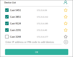
Display Group Settings
To adjust the Display Group Settings, select the Display Group icon ![]() located in the lower-right corner of the screen.
located in the lower-right corner of the screen.

- Toggle the “Turn On/Off Display Group” ON to enable the Display Group feature.
 Note: Other preinstalled-vCast devices in the same network will be listed.
 - Select the devices you want to join the display group and select OK to save the settings.
 Note:
Note:- If the devices you want to group are not listed, you can enter their respective IP address or connecting PIN code.
- The Display Group maximum device limit is six devices.
- If you frequently connect to the same device, you can select the Star icon next to the device to add it to your frequently connected devices list, “My List of Devices in Group”, for easier Display Group setup and management.


Synchronized Group Screen All the Time
When the “Synchronized group screen all the time” function is toggled ON, it will display a synchronized group screen continuously. If it is toggled OFF, it will work on vCast mirroring only.

After confirming the above settings, you can share your screen to the main display, then the grouped client devices will be synced up to your screen.

Moderator Mode
Moderator Mode allows the moderator to take control of the devices connected to the display. To enter Moderator Mode, select the Moderator Mode icon ![]() located in the lower-right corner of the screen.
located in the lower-right corner of the screen.

When enabled, the moderator can view a list of all connected screens in the left floating window and can preview each participant’s screen and then select any of participant’s screen and cast to the display's main screen for presentation. The moderator can also control each participant’s screen, annotate on the display, and remove unwanted participants by selecting the close icon .

Broadcast
When enabled, the display's screen will be broadcasted to all of the participant’s connected screens simultaneously. The participants can only view the presentation contents until the moderator disables the Broadcast function.

Multiple Screen Sharing
By default, vCast is set to allow multiple screen sharing, but can also be set to single screen sharing. To do this, the moderator can select the Multiple Screen Sharing icon to switch to single screen sharing.
Preview Screen
By default, vCast is set to let the moderator preview the participant’s screen contents prior to sharing to the display. Selecting the Preview Screen icon, the Moderator can switch to see the participant’s name only.
Touch
By default, participants can use touch for collaboration after connecting. The moderator can enable/disable the touch function of a participant by selecting the Touch icon in their window.
- Moderator Mode is supported on all vCastSender and AirPlay devices, but mobile devices are limited to a "preview" function. Additionally, mobile Android devices cannot cast sound out.
- When you cast your Windows/Mac/Chrome screen to a display, the selected full screen unit will not be broadcasted back to your device to avoid repetitive screen casting.
- The active presenter can touch each of the participant's screens to remotely control casting devices.
- The number of multi-screen presenters on-screen depends on your Windows CPU processor performance and router specifications.
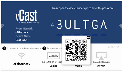
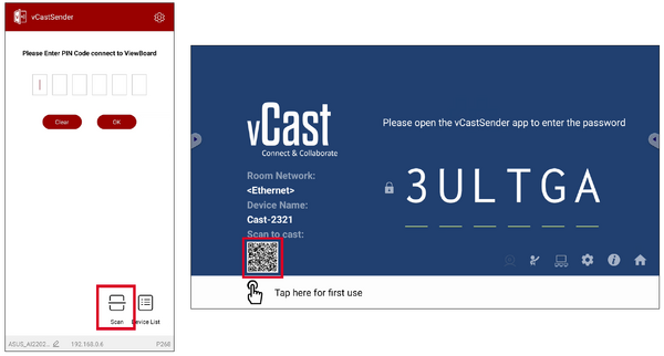
Casting from Windows, MacBook, and Chrome Devices

- Ensure the client device (e.g., laptop) is connected to the same network as the display.
- On the client device, visit the address that is shown on the display to download and install the vCastSender application.
- After installing, launch the vCastSender application.
- To connect to the display, input the PIN code and click OK.
- Additionally, you can connect to the display by clicking Device List then the Device Name listed.


Casting from Android Devices

- Ensure the client device (e.g., Android phone or tablet) is connected to the same network as the display.
- On the Android client device, scan the QR code shown on the display to directly download the vCastSender application, or download the application from the Google Play Store.
- After installing, launch the vCastSender application.
- To connect to the display, input the PIN code and select OK.
- You can also connect to the display by clicking Device List then the Device Name listed.
- Additionally, you can connect to the display by selecting Scan then placing the on-screen QR code into the box to automatically connect.


Casting from Apple iOS Devices
Apple AirPlay® is compatible with vCast for screen mirroring and content streaming under the same subnet environment only. An “AirPlay Password” will be generated on-screen for connection when using AirPlay to cast to a display.

- Ensure the client device (e.g., iPhone or iPad) is connected to the same network as the display.
- On the iOS client device, directly open AirPlay and select the Device Name of the display to connect.
- Input the generated on-screen AirPlay Password on the client device to connect.
- You can also connect to the display by selecting Scan then placing the on-screen QR code into the box to automatically connect.

Connecting to a Display from Mobile Device
Once connected, select Receive. The selected display screen will appear on the mobile device with an on-screen toolbar. Users can interact with the display with annotations, file sharing, etc.

| Item | Description | |
|---|---|---|
| Toggle | Hide or display the toolbar. | |
| Home | Return to the Home interface. | |
| Return | Return to the previous operation. | |
| Folder | View or open the mobile device's files. | |
| Share | Cast the mobile device's screen to the connected display. | |
| Touch | Remotely control the connected display. | |
| Annotate | Make annotations, and adjust the pen color. | |
| Clear | Clear everything on screen. | |
| Camera | Send camera images to the connected display. | |
Casting with Chromecast
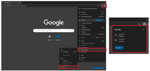
vCast supports native Chromecast screen sharing via the Chrome browser casting when the Chromecast feature is enabled.
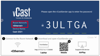
- Ensure the client device (e.g., laptop) is connected to the same network as the display.
Note: The network name can be found under Room Network.
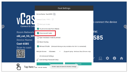
- Ensure the Chromecast Enable checkbox is selected in the vCast settings.
- In the Chrome browser, go to: Settings > Save and share > Cast... > Select the screen to cast to.


Casting with Miracast
vCast supports native Miracast to cast content from Windows and Android devices to a display when the Miracast feature is enabled.
- Miracast does not support password protection or multiple-screen casting.
- Miracast sharing is only available over Wi-Fi.
- Miracast will automatically turn off after being idle for one hour.
- Ensure the client device (e.g., laptop) is connected to the same network as the display.
Note: The network name can be found under Room Network.
- Ensure the Miracast Enable checkbox is selected in the vCast settings.
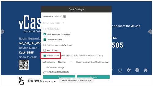
- Please follow the below steps to cast:
For Windows devices:
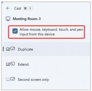
- On the Windows device, press Win + K and select the display to cast to.
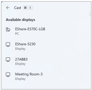
- Select the checkbox “Allow mouse, keyboard, touch, and pen input from the device” to enable the touch feedback feature.
For Android devices:
On the Android device, directly select Cast/Smart View/Wireless Projection then select the display to cast to. - On the Windows device, press Win + K and select the display to cast to.


Other Default Applications
Browser
Web browser for surfing the internet.

Office Suite
Create, edit, and view Documents, Spreadsheets, Presentations, and PDFs.


vSweeper
Clear unnecessary data and unwanted files.
Advanced Settings can also be customized to the user's needs.

Technical Specifications

| Model No. | P/N |
|---|---|
| VS18881 | LDS135-153 |
| Item | Category | Specifications | |||
|---|---|---|---|---|---|
| Model | LDS135-153 | ||||
| LED Screen | Type | Direct View LED Display | |||
| Size | 135” | ||||
| Active Size | 118.11” (H) x 66.44” (V) 3,000 mm (H) x 1,687.5 mm(V) | ||||
| Pitch Size | 1.56 mm | ||||
| Resolution | FHD, 1920 x 1080 | ||||
| Refresh Rate | up to 3840 Hz | ||||
| Contrast Ratio | 6000:1 (Typical) | ||||
| Brightness | 100-600 cd/m2 | ||||
| Input Signal | 6 x HDMI (1920 x 1080 @ 60Hz, HDCP 2.2) 1 x LAN (RJ45) 3 x USB Type A (2.0) 1 x USB Type C (5V/2A) 1 x IR in | ||||
| Output Signal | 2 x HDMI (1080p @ 60Hz) 1 x Audio Out (3.5 mm) 3 x USB Type A (Power) [5V/1.5A] | ||||
| Speaker Output | 2 x 20W Harman Kardon Speakers | ||||
| Power | Voltage | 100V-120V/30A ~ 50/60Hz 220-240V/15A ~ 50Hz (vary by country) | |||
| Operating Conditions | Temperature | 32° F to 104° F (0° C to 40° C) | |||
| Humidity | 20%~80% non-condensing | ||||
| Altitude | ≤ 6,562 ft (2,000 m) | ||||
| Storage Conditions | Temperature | -4° F to 140° F (-20° C to 60° C) | |||
| Humidity | 10%~90% non-condensing | ||||
| Altitude | ≤ 6,562 ft (2,000 m) | ||||
| Physical Dimensions (W x H x D) |
Without Flight Case | 1,800~3,010 x 2,022.8~2,690 x 760 mm
(70.87"~118.5” x 79.64"~105.91” x 29.92”) | |||
| With Flight Case | 1,900 x 2,052 x 800 mm
(74.80" x 80.79" x 31.50") | ||||
| Weight | Physical | 249 lbs. (548.95 kg) | |||
LED Display Stuck Pixel Definition
| Item | Acceptance Criteria |
|---|---|
| Stuck Pixel (whole display) |
≤ 60 stuck pixels |
| Stuck Pixel (as marked in green) |
≤ 15 stuck pixels |
| Stuck Pixel (Single Module) |
≤ 6 stuck pixels |
Timing Chart
HDMI (PC)
| Resolution | Refresh Rate (Hz) |
|---|---|
| 640 x 480 | 60, 72, 75 |
| 720 x 400 | 70, 85 |
| 800 x 600 | 56, 60, 72, 75 |
| 832 x 624 | 75 |
| 1024 x 768 | 60, 70, 75 |
| 1152 x 864 | 60, 70, 75 |
| 1152 x 870 | 75 |
| 1280 x 720 | 60 |
| 1280 x 960 | 60 |
| 1280 x 1024 | 60, 75 |
| 1360 x 768 | 85 |
| 1440 x 900 | 60 |
| 1600 x 1200 | 60, 70, 75 |
| 1680 x 1050 | 60 |
| 1920 x 1080 | 60 |
| 1920 x 1200 | 60 |
| 3840 x 2160 | 30, 60 |
HDMI (Video)
| Video | Resolution | Refresh Rate (Hz) |
|---|---|---|
| 480i | 720 x 480 | 60 |
| 1440 x 480 | 60 | |
| 576i | 720 x 576 | 50 |
| 1440 x 576 | 50 | |
| 480p | 720 x 480 | 60 |
| 576p | 720 x 576 | 50 |
| 1440 x 576 | 50 | |
| 720p | 1280 x 720 | 60 |
| 1080i | 1920 x 1080 | 50, 60 |
| 1080p | 1920 x 1080 | 24, 25, 30, 50, 60 |
| 2160p | 3840 x 2160 | 30, 60 |
- The computer text quality is optimal in HD 1080 mode (1920 x 1080, 60Hz).
- Your computer display screen might appear different depending on the manufacturer and your operating system.
- Consult your computer’s instructional manual on how to connect to an external display if needed.
- If a vertical and horizontal frequency-select mode exists, select 60Hz (vertical) and 67.5KHz(horizontal). In some cases, abnormal signals (such as stripes) might appear on the screen when the computer power is turned off (or if the computer is disconnected). If this is the case, press the [INPUT SOURCE] button to enter the video mode and supply an active signal.
- The display timings conform to VESA and CTA standards.
- For 4:3 content, the screen will display them in the center of the screen and maintain a 4:3 aspect ratio.
- The optimal vertical frequency for each mode is 60Hz.
Supported Media Formats
Multimedia Codec Formats
| Type | File Type | Codec | Ability |
|---|---|---|---|
| Photo | PNG | Max Resolution: 8000 × 8000 Min Resolution : 4 x 4 | |
| JPEG/JPG | Max Resolution: 8000 × 8000 Min Resolution: 4 x 4[1] | ||
| Video | .3gp | H.263 | Max Resolution: 1920 x 1080 30 Hz Audio: AMR_NB |
| MPEG-4 | Max Resolution: 1920 x 1080 30 Hz Audio: AMR_NB | ||
| .avi | MPEG-2/4 | Max Resolution: 1920 x 1080 30 Hz Audio: MPEG_Audio_Layer3 | |
| MJPEG | Max Resolution: 1920 x 1080 30 Hz Audio: MPEG_Audio_Layer3 | ||
| .flv | H.264 | Max Resolution: 1920 x 1080 30 Hz Audio: AAC 2.0 | |
| .mkv | H.264 | Max Resolution: 1920 x 1080 30 Hz Audio: AAC 2.0 | |
| H.265 | Max Resolution: 1920 x 1080 30 Hz Audio: AAC 2.0 | ||
| .mp4 | H.264 | Max Resolution: 3840 x 2160 30 Hz Audio: MPEG_Audio_Layer3 | |
| H.265 | Max Resolution: 3840 x 2160 30 Hz Audio: MPEG_Audio_Layer3 | ||
| MPEG-4 | Max Resolution: 1920 x 1080 30 Hz Audio: MPEG_Audio_Layer3 | ||
| .vob | MPEG-2 | Max Resolution: 1920 x 1080 30 Audio: PCM | |
| .mpg/.mpeg | MPEG-2 | Max Resolution: 1920 x 1080 30 Hz Audio: MPEG_Audio_Layer3 | |
| Audio | .aac | GAAC | Sample Rate: 8K~96KHz Bit Rate: 24K~576Kbps |
| .ape | Monkey's Audio | Sample Rate: max 48KHz Bit Rate: max 1411Kbps | |
| .flac | FLAC | Sample Rate: max 192KHz Bit Rate: max 1411Kbps | |
| .m4a | ALAC | Sample Rate: 8K~96KHz Bit Rate: 24K~576Kbps | |
| .mp3 | MPEG1/2 layer 3 | Sample Rate: 8K~48KHz Bit Rate: 32K~320Kbps | |
| .ogg | Vorbis | Sample Rate: 8K~48KHz Bit Rate: max 256Kbps | |
| .wav | LPCM | Sample Rate: 8K~192KHz Bit Rate: max 320Kbps |
Compliance Information
This section addresses all connected requirements and statements regarding regulations. Confirmed corresponding applications shall refer to nameplate labels and relevant markings on the unit.
FCC Compliance Statement
This device complies with part 15 of FCC Rules. Operation is subject to the following two conditions: (1) this device may not cause harmful interference, and (2) this device must accept any interference received, including interference that may cause undesired operation. This equipment has been tested and found to comply with the limits for a Class B digital device, pursuant to part 15 of the FCC Rules.
These limits are designed to provide reasonable protection against harmful interference in a residential installation. This equipment generates, uses, and can radiate radio frequency energy, and if not installed and used in accordance with the instructions, may cause harmful interference to radio communications. However, there is no guarantee that interference will not occur in a particular installation. If this equipment does cause harmful interference to radio or television reception, which can be determined by turning the equipment off and on, the user is encouraged to try to correct the interference by one or more of the following measures:
- Reorient or relocate the receiving antenna.
- Increase the separation between the equipment and receiver.
- Connect the equipment into an outlet on a circuit different from that to which the receiver is connected.
- Consult the dealer or an experienced radio/TV technician for help.
The antenna(s) used for this transmitter must not be collocated or operating in conjunction with any other antenna or transmitter.
The device was tested and complies to measurement standards and procedures specified in FCC CFR Tile 47 Part 15 Subpart C.
FCC Radiation Exposure Statement
This equipment complies with FCC radiation exposure limits set forth for an uncontrolled environment. End users must follow the specific operating instructions for satisfying RF exposure compliance.
This transmitter must not be co-located or operating in conjunction with any other antenna or transmitter. This equipment should be installed and operated with a minimum distance of 20 centimeters between the radiator and your body.
The users manual or instruction manual for an intentional or unintentional radiator shall caution the user that changes or modifications not expressly approved by the party responsible for compliance could void the user’s authority to operate the equipment.IC Warning Statement
This device complies with Industry Canada license- exempt RSS standard(s). Operation is subject to the following two conditions: (1) this device may not cause interference, and (2) this device must accept any interference, including interference that may cause undesired operation of the device.
Le présent appareil est conforme aux CNR d’Industrie Canada applicables aux appareils radio exempts de licence. L’exploitation est autorisée aux deux conditions suivantes : ( 1 ) l’appareil ne doit pas produire de brouillage, et ( 2) l’utilisateur de l’appareil doit accepter tout brouillage radioélectrique subi, méme si le brouillage est susceptible d’en compromettre le fonctionnement.
Country Code Statement
For product available in the USA/Canada market, only channel 1~11 can be operated. Selection of other channels is not possible.
Pour les produits disponibles aux États-Unis/Canada du marché, seul le canal 1 à 11 peuvent être exploités. Sélection d’autres canaux n’est pas possible.
IC Radiation Exposure Statement
This equipment complied with IC RSS-102 radiation exposure limits set forth for an uncontrolled environment. This equipment should be installed and operated with minimum distance 20cm between the radiator & your body. The device for the band 5150-5825 MHz is only for indoor usage to reduce potential for harmful interference to co-channel mobile satellite systems.
Cet équipement est conforme aux limites d’exposition aux rayonnements IC établies pour un environnement non contrôlê. Cet équipement doit être installé et utilize avec un minimum de 20cm de distance entre la source de rayonnement et votre corps. les dispositifs fonctionnant dans la bande 5150-5825 MHz sont réservés uniquement pour une utilisation à l’intérieur afin de réduire les risques de brouillage préjudiciable aux systèmes de satellites mobiles utilisant les mêmes canaux.
Industry Canada Statement
CAN ICES(B) / NMB(B)
CE Conformity for European Countries
| The device complies with the EMC Directive 2014/30/EU and Low Voltage Directive 2014/35/EU. |
| The mark shown to the right is in compliance with the Waste Electrical and Electronic Equipment Directive 2012/19/EU (WEEE). The mark indicates the requirement NOT to dispose of the equipment as unsorted municipal waste, but use the return and collection systems according to local law. |
Declaration of RoHS2 Compliance
This product has been designed and manufactured in compliance with Directive 2011/65/EU of the European Parliament and the Council on restriction of the use of certain hazardous substances in electrical and electronic equipment (RoHS2 Directive) and is deemed to comply with the maximum concentration values issued by the European Technical Adaptation Committee (TAC) as shown below:
| Substance | Proposed Maximum Concentration | Actual Concentration |
|---|---|---|
| Lead (Pb) | 0.1% | < 0.1% |
| Mercury (Hg) | 0.1% | < 0.1% |
| Cadmium (Cd) | 0.01% | < 0.01% |
| Hexavalent Chromium (Cr6⁺) | 0.1% | < 0.1% |
| Polybrominated biphenyls (PBB) | 0.1% | < 0.1% |
| Polybrominated diphenyl ethers (PBDE) | 0.1% | < 0.1% |
| Bis (2-ethylhexyl) phthalate (DEHP) | 0.1% | < 0.1% |
| Butyl benzyl phthalate (BBP) | 0.1% | < 0.1% |
| Dibutyl phthalate (DBP) | 0.1% | < 0.1% |
| Diisobutyl phthalate (DIBP) | 0.1% | < 0.1% |
- Copper alloy containing up to 4% lead by weight.
- Lead in high melting temperature type solders (i.e. lead-based alloys containing 85% by weight or more lead).
- Electrical and electronic components containing lead in a glass or ceramic other than dielectric ceramic in capacitors, e.g. piezoelectronic devices, or in a glass or ceramic matrix compound.
- Lead in dielectric ceramic in capacitors for a rated voltage of 125V AC or 250V DC or higher.
European Union Regulatory Conformance
The equipment complies with the RF Exposure Requirement 2014/53/EU, Council Recommendation of 16 April 2014 on the limitation of exposure of the general public to electromagnetic fields (0-300 GHz). This equipment meets the following conformance standards: EN301489-1, EN301489-17, EN62368-1, EN300328.
We, hereby, declare that this Wi-Fi radio is in compliance with the essential requirements and other relevant provisions of Directive 2014/53/EU.
Indian Restriction of Hazardous Substances
Restriction on Hazardous Substances statement (India). This product complies with the “India E-waste Rule 2011” and prohibits use of lead, mercury, hexavalent chromium, polybrominated biphenyls or polybrominated diphenyl ethers in concentrations exceeding 0.1 weight % and 0.01 weight % for cadmium, except for the exemptions set in Schedule 2 of the Rule.
Product Disposal at End of Product Life
ViewSonic® respects the environment and is committed to working and living green. Thank you for being part of Smarter, Greener Computing. Please visit the ViewSonic® website to learn more.
USA & Canada:
https://www.viewsonic.com/us/go-green-with-viewsonic
Europe:
https://www.viewsonic.com/eu/environmental-social-governance/recycle
Taiwan:
https://recycle.moenv.gov.tw/
For EU users, please contact us for any safety/accident issue experienced with this product:
| ViewSonic Europe Limited Haaksbergweg 75 1101 BR Amsterdam Netherlands | |
| +31 (0) 650608655 | |
| EPREL@viewsoniceurope.com | |
| https://www.viewsonic.com/eu/ |
Copyright Information
Copyright© ViewSonic® Corporation, 2024. All rights reserved.
Macintosh and Power Macintosh are registered trademarks of Apple Inc.
Microsoft, Windows, and the Windows logo are registered trademarks of Microsoft Corporation in the United States and other countries.
ViewSonic® and the three birds logo are registered trademarks of ViewSonic® Corporation.
VESA is a registered trademark of the Video Electronics Standards Association. DPMS, DisplayPort, and DDC are trademarks of VESA.
CTA is a registered trademark of the Consumer Technology Association Standards.
Disclaimer: ViewSonic® Corporation shall not be liable for technical or editorial errors or omissions contained herein; nor for incidental or consequential damages resulting from furnishing this material, or the performance or use of this product.
In the interest of continuing product improvement, ViewSonic® Corporation reserves the right to change product specifications without notice. Information in this document may change without notice.
No part of this document may be copied, reproduced, or transmitted by any means, for any purpose without prior written permission from ViewSonic® Corporation.
LDS135-153_UG_ENG_1a_20240429
For technical support or product service, see the table below or contact your reseller.
Americas
| Country/Region | Website |
|---|---|
| Canada | https://www.viewsonic.com/us |
| Latin America | https://www.viewsonic.com/la |
| United States | https://www.viewsonic.com/us |
Asia Pacific & Africa
| Country/Region | Website |
|---|---|
| Australia | https://viewsonic.com/au/ |
| Bangladesh | https://www.viewsonic.com/bd/ |
| 中国 (China) | https://www.viewsonic.com.cn |
| 香港 (繁體中文) | https://www.viewsonic.com/hk/ |
| Hong Kong (English) | https://www.viewsonic.com/hk-en/ |
| India | https://www.viewsonic.com/in/ |
| Indonesia | https://www.viewsonic.com/id/ |
| Israel | https://www.viewsonic.com/il/ |
| 日本 (Japan) | https://www.viewsonic.com/jp/ |
| Korea | https://www.viewsonic.com/kr/ |
| Malaysia | https://www.viewsonic.com/my/ |
| Middle East | https://www.viewsonic.com/me/ |
| Myanmar | https://www.viewsonic.com/mm/ |
| Nepal | https://www.viewsonic.com/np/ |
| New Zealand | https://www.viewsonic.com/nz/ |
| Pakistan | https://www.viewsonic.com/pk/ |
| Philippines | https://www.viewsonic.com/ph/ |
| Singapore | https://www.viewsonic.com/sg/ |
| 臺灣 (Taiwan) | https://www.viewsonic.com/tw/ |
| ประเทศไทย | https://www.viewsonic.com/th/ |
| Việt Nam | https://www.viewsonic.com/vn/ |
| South Africa & Mauritius | https://www.viewsonic.com/za/ |
Europe
| Country/Region | Website |
|---|---|
| Europe | https://www.viewsonic.com/eu/ |
| France | https://www.viewsonic.com/fr/ |
| Deutschland | https://www.viewsonic.com/de/ |
| Қазақстан | https://www.viewsonic.com/kz/ |
| Россия | https://www.viewsonic.com/ru/ |
| España | https://www.viewsonic.com/es/ |
| Türkiye | https://www.viewsonic.com/tr/ |
| Україна | https://www.viewsonic.com/ua/ |
| United Kingdom | https://www.viewsonic.com/uk/ |
Limited Warranty
ViewSonic® Commercial Display
What the warranty covers:
ViewSonic® warrants its products to be free from defects in material and workmanship during the warranty period. If a product proves to be defective in material or workmanship during the warranty period, ViewSonic® will, at its sole option, and as your sole remedy, repair or replace the product with a similar product. Replacement Product or parts may include remanufactured or refurbished parts or components. The repair or replacement unit or parts or components will be covered by the balance of the time remaining on the customer’s original limited warranty and the warranty period will not be extended. ViewSonic® provides no warranty for any third-party software whether included with the product or installed by the customer, installation of any unauthorized hardware parts or components (e.g. Projector Lamps). (Please refer to: “What the warranty excludes and does not cover” section).
Who the warranty protects:
This warranty is valid only for the first consumer purchaser.
What the warranty excludes and does not cover:
- Any product on which the serial number has been defaced, modified, or removed.
- Damage, deterioration, or malfunction resulting from:
- Accident, misuse, neglect, fire, water, lightning, or other acts of nature, unauthorized product modification, or failure to follow instructions supplied with the product.
- Repair or attempted repair by anyone not authorized by ViewSonic®.
- Damage to or loss of any programs, data, or removable storage media.
- Normal wear and tear.
- Removal or installation of the product.
- Software or data loss occurring during repair or replacement.
- Any damage of the product due to shipment.
- Causes external to the product, such as electric power fluctuations or failure.
- Use of supplies or parts not meeting ViewSonic’s specifications.
- Failure of owner to perform periodic product maintenance as stated in the User Guide.
- Any other cause which does not relate to a product defect.
- Damage caused by static (non-moving) images displayed for lengthy periods of time (also referred to as image burn-in).
- Software - Any third-party software included with the product or installed by the customer.
- Hardware/Accessories/Parts/Components – Installation of any unauthorized hardware, accessories, consumable parts or components (e.g. Projector Lamps).
- Damage to, or abuse of, the coating on the surface of the display through inappropriate cleaning as described in the product User Guide.
- Removal, installation, and set-up service charges, including wall-mounting of the product.
How to get service:
- For information about receiving service under warranty, contact ViewSonic® Customer Support (Please refer to the “Customer Service” page). You will need to provide your product’s serial number.
- To obtain warranty service, you will be required to provide: (a) the original dated sales slip, (b) your name, (c) your address, (d) a description of the problem, and (e) the serial number of the product.
- Take or ship the product, freight prepaid, in the original container to an authorized ViewSonic® service center or ViewSonic®.
- For additional information or the name of the nearest ViewSonic® service center, contact ViewSonic®.
Limitation of implied warranties:
There are no warranties, express or implied, which extend beyond the description contained herein including the implied warranty of merchantability and fitness for a particular purpose.
Exclusion of damages:
ViewSonic’s liability is limited to the cost of repair or replacement of the product. ViewSonic® shall not be liable for:
- Damage to other property caused by any defects in the product, damages based upon inconvenience, loss of use of the product, loss of time, loss of profits, loss of business opportunity, loss of goodwill, interference with business relationships, or other commercial loss, even if advised of the possibility of such damages.
- Any other damages, whether incidental, consequential or otherwise.
- Any claim against the customer by any other party.
- Repair or attempted repair by anyone not authorized by ViewSonic®.
Effect of state law:
This warranty gives you specific legal rights, and you may also have other rights which vary from state to state. Some states do not allow limitations on implied warranties and/or do not allow the exclusion of incidental or consequential damages, so the above limitations and exclusions may not apply to you.
Sales outside the U.S.A. and Canada:
For warranty information and service on ViewSonic® products sold outside of the U.S.A. and Canada, contact ViewSonic® or your local ViewSonic® dealer.
The warranty period for this product in mainland China (Hong Kong, Macao, and Taiwan Excluded) is subject to the terms and conditions of the Maintenance Guarantee Card.
For users in Europe and Russia, full details of warranty provided can be found at: http://www.viewsonic.com/eu/ under “Support/Warranty Information”.
Mexico Limited Warranty
ViewSonic® Commercial Display
What the warranty covers:
ViewSonic® warrants its products to be free from defects in material and workmanship, under normal use, during the warranty period. If a product proves to be defective in material or workmanship during the warranty period, ViewSonic® will, at its sole option, repair or replace the product with a like product. Replacement product or parts may include remanufactured or refurbished parts or components & accessories.
Who the warranty protects:
This warranty is valid only for the first consumer purchaser.
What the warranty excludes and does not cover:
- Any product on which the serial number has been defaced, modified or removed.
- Damage, deterioration, or malfunction resulting from:
- Accident, misuse, neglect, fire, water, lightning, or other acts of nature, unauthorized product modification, unauthorized attempted repair, or failure to follow instructions supplied with the product.
- Causes external to the product, such as electrical power fluctuations or failure.
- Use of supplies or parts not meeting ViewSonic®’s specifications.
- Normal wear and tear.
- Any other cause which does not relate to a product defect.
- Any product exhibiting a condition commonly known as “image burn-in” which results when a static image is displayed on the product for an extended period of time.
- Removal, installation, insurance, and set-up service charges.
How to get service:
- For information about receiving service under warranty, contact ViewSonic® Customer Support (Please refer to the “Customer Service” page). You will need to provide your product’s serial number, so please record the product information in the space provided below on your purchase for your future use. Please retain your receipt of proof of purchase to support your warranty claim.
- To obtain warranty service, you will be required to provide: (a) the original dated sales slip, (b) your name, (c) your address, (d) a description of the problem, and (e) the serial number of the product.
- Take or ship the product, freight prepaid, in the original container to an authorized ViewSonic® service center.
- Round trip transportation costs for in-warranty products will be paid by ViewSonic®.
Limitation of implied warranties:
There are no warranties, express or implied, which extend beyond the description contained herein including the implied warranty of merchantability and fitness for a particular purpose.
Exclusion of damages:
ViewSonic®’s liability is limited to the cost of repair or replacement of the product. ViewSonic® shall not be liable for:
- Damage to other property caused by any defects in the product, damages based upon inconvenience, loss of use of the product, loss of time, loss of profits, loss of business opportunity, loss of goodwill, interference with business relationships, or other commercial loss, even if advised of the possibility of such damages.
- Any other damages, whether incidental, consequential or otherwise.
- Any claim against the customer by any other party.
- Repair or attempted repair by anyone not authorized by ViewSonic®.
| Contact Information for Sales & Authorized Service (Centro Autorizado de Servicio) within Mexico: | |
|---|---|
|
Name, address, of manufacturer and importers:
| |
| NÚMERO GRATIS DE ASISTENCIA TÉCNICA PARA TODO MÉXICO: 001.866.823.2004 | |
|
Hermosillo:
|
Villahermosa:
|
|
Puebla, Pue. (Matriz):
|
Veracruz, Ver.:
|
|
Chihuahua:
|
Cuernavaca:
|
|
Distrito Federal:
|
Guadalajara, Jal.:
|
|
Guerrero Acapulco:
|
Monterrey:
|
|
MERIDA:
|
Oaxaca, Oax.:
|
|
Tijuana:
|
FOR USA SUPPORT:
|
Using the Direct View LED Display Safely
Please read the following Safety Precautions before you start using the device.
|
|
Troubleshooting Common Problems
General
Why isn't the remote control working?
Solution 1 ► Check whether something is obstructing the display’s remote control receiver.
Solution 2 ► Check whether the battery polarities in the remote control are installed correctly.
Solution 3 ► Check whether the batteries need to be replaced.
What should I do if the device just turns off unexpectedly?
Solution 1 ► Check whether Sleep mode is enabled.
Solution 2 ► Check if there is a power outage in your area.
Solution 3 ► Turn on the display, provide an active signal, and see if the problem is with the signal or external control system.
What should I do if the power indicator is off and there is no response?
Solution 1 ► Ensure the power cable is connected and not loose.
Solution 2 ► Check that the power outlet is functioning properly and meets the required electrical requirement.
Why does the display not recognize the USB storage device?
Solution 1 ► Ensure the drive is either formatted for FAT32 or NTFS.
Solution 2 ► If the USB storage device needs external power, connect its power adapter to an electrical outlet.
Video Not Working Properly
Why is there no picure or sound?
Solution 1 ► Check the Power status.
Solution 2 ► Check the signal cable.
Solution 3 ► Use the remote control to ensure the input source setting is the same as the connected device.
What should I do if the picture is unclear or cuts in and out?
Solution 1 ► Check the signal cable.
Solution 2 ► Check if other electronics or different signal types are interrupting the signal.
Solution 3 ► An optional active video cable or optional video extender is required for a long distance source.
What should I do if the picture quality is poor?
Solution 1 ► Adjust chroma and/or brightness settings in the menu.
Solution 2 ► Check the signal cable.
Solution 3 ► Use the display’s native resolution for the source.
Audio Not Working Properly
Why is there no sound?
Solution 1 ► Press the Mute/Unmute button.
Solution 2 ► Adjust the volume.
Solution 3 ► Check the audio cable connection (if used).
Solution 4 ► If using a computer digital video with embedded audio, ensure the computer speakers are set to external speakers.
What should I do if sound is only coming from one speaker?
Solution 1 ► Adjust the sound balance in the menu.
Solution 2 ► Check the left and right sound control panel settings of the computer or media player source.
Solution 3 ► Check the audio cable connection (if used).
Solution 4 ► Ensure the content has two audio channels and not mono.
Maintaining the LED Display
General Precautions
- The LED lights used in the modules are susceptible to ESD (Electrostatic discharge). To prevent damage to the LED lights, do not touch them with bare hands or with conductive materials when handling.
- It is recommended to regularly inspect all installed components.
- Do not bring objects close to the ventilation holes of the display. Burns or personal injuries may occur if any body parts are brought too close.
- Be sure to power off and disconnect all cables before moving the display. Moving the display with its cables attached may damage the cables and thus cause fire or electric shock.
- Power off and disconnect the power plug from the wall outlet as a safety precaution before performing any type of cleaning or maintenance.
Initial Operation
- If a new screen has been stowed for less than three (3) months, it can be used at normal brightness during its first use.
- If a new screen has been stowed for more than three (3) months, the brightness should be set at 30% for its first use and allowed to operate for two (2) hours continuously. After two (2) hours of use, power off for 30 minutes. The new screen is now ready for normal brightness usage.
Front Panel Cleaning Instructions
- Use cool, compressed air to remove dust when the power is off. If the dust cannot be removed, the LED module should be replaced.
- Do not scratch and do not put pressure on the panel surface with fingers or any abrasive object.
- Do not use volatile substances such as sprays, solvents, or thinners.
Cabinet Cleaning Instructions
- Do not allow water or detergent to come into contact with the surface of the display. If water or moisture gets inside the unit, a system malfunction or electrical shock may occur.
- Do not scratch and do not put pressure on the cabinet with any abrasive objects of any kind.
- Do not use volatile substances such as sprays, solvents, or thinners on the cabinet.
- Do not place anything made from rubber or PVC near the cabinet for any extended periods of time.
Regular Use
- It is recommended to turn on the display at least once a month for more than eight (8) hours. During a wet and rainy season, it is recommended to turn on the display at least once a week.
- Avoid using full white, full red, full blue, or full green content for an extended period to avoid excessive power usage thus affecting the LED lifespan.
- ↑ Progressive support 4000 × 4000; baseline support 8000 x 8000.